

What Are the Signs of a Malfunctioning Level Transmitter Circuit Module?
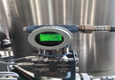
In 2026, chemical plants, petrochemical facilities, and storage sites need more than a level reading. They need stable data for tank control, overflow prevention, material planning, and process safety. When the reading becomes unstable, many engineers first inspect the probe or the complete level transmitter. However, the problem may be inside the level transmitter circuit module.
A complete level transmitter includes the probe, housing, process connection, wiring, display, and electronic circuit. The transmitter board is the electronic core that receives the sensor signal, filters interference, calculates level, and sends information to the control system.
At ICwalk, we provide transmitter boards and electronic modules for instrument manufacturers. This article focuses on the H509 capacitive level transmitter board and explains the common signs of a malfunctioning circuit module.
What Does a Level Transmitter Circuit Module Do?
The circuit module sits between the level sensor and the control system. It does not replace the tank probe, enclosure, or process connection. Instead, it turns a small and sometimes unstable sensor signal into useful industrial data for the operator, PLC, or DCS.
A process control board transmitter may manage signal conditioning, calibration, temperature effects, output conversion, fault detection, and digital communication. This work is easy to overlook because the board is hidden inside the finished field transmitter. Yet its performance directly affects the reliability of the final instrument.
The Board Is the Measurement Core
A capacitive level instrument detects changes in capacitance caused by the height or presence of a liquid or solid material. The transmitter board must interpret these changes while dealing with cable capacitance, coating, electrical noise, grounding differences, and changes in the process medium.
For teams asking “what is it for,” the answer is simple: the circuit module converts the raw sensor response into a stable level value. It can also provide 4-20mA output, HART communication, local display data, alarms, and configuration functions.
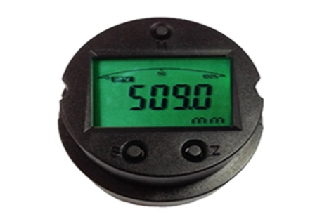
The H509 uses capacitive measurement technology and is designed as the core component of a level gauge. It supports industrial level applications in areas such as petroleum, chemical processing, water treatment, food, pharmaceuticals, and natural gas.
Why the Complete Instrument Still Matters
A level transmitter board cannot correct every mechanical or process problem. A damaged probe, unsuitable process material, heavy buildup, poor grounding, or incorrect installation can make a healthy board appear faulty.
For corrosive or toxic liquids, the finished instrument requires suitable probe materials, seals, process connections, enclosure protection, and maintenance procedures. In flammable or explosive areas, the instrument manufacturer must also complete the required system-level safety design and certification.
What Are the Signs of a Malfunctioning Module?
A circuit module may fail completely, but many faults appear gradually. The reading may drift, the output may become unstable, or communication may stop while the display still shows a believable value. These symptoms can confuse maintenance teams because the instrument has not stopped working in an obvious way.
The best approach is to compare the indication, analog output, digital data, and actual process condition. If these values do not agree, the signal path needs a closer inspection.
Unstable or Incorrect Level Readings
An unstable reading is one of the most common signs of a problem. The displayed level may jump even when the tank condition is steady. It may also remain fixed, respond too slowly, or show a value that does not match a manual measurement.
Possible causes include:
- Damaged sensor input components
- Poor signal conditioning
- Moisture or corrosion on the circuit
- Electromagnetic interference
- Incorrect range or damping settings
- Heavy material buildup on the probe
- Unstable power supply or grounding
A faulty Sensor Signal Conditioning Board may amplify noise together with the useful capacitance signal. The result can look like a process change even when the actual liquid level has not moved.
Wrong 4-20mA Output or HART Data
The display may look normal while the control system receives the wrong value. This often points to an output circuit, configuration, wiring, or communication problem.
A 4-20mA Transmitter Board should provide a stable current that matches the configured level range. If the output is too low, too high, or constantly fluctuates, engineers should compare the current value with the displayed variable and the process condition.
HART communication provides another useful check. If a HART Protocol Module is not responding, technicians may lose access to range settings, diagnostic information, damping, or calibration data. A failed communication link does not always mean the sensor is damaged. The problem may be in the loop resistance, wiring, power supply, or board interface.
The H509 includes self-test behavior that can set the current output to 3.8mA or 22.0mA when a fault is detected. This gives the control system a clear abnormal signal instead of silently passing unreliable data.
How Should Engineers Check the Fault?
Replacing the complete level transmitter may solve the immediate problem, but it can also hide the real cause. A structured inspection helps plant teams decide whether the issue is related to the process, sensor, cable, power loop, configuration, or circuit module.
The inspection should move from the outside of the system toward the electronics. This reduces unnecessary disassembly and is especially useful when the instrument is installed near corrosive chemicals, toxic media, or restricted process equipment.
Check the Process and Sensor First
Begin with the physical measurement conditions. Confirm whether the tank level is actually changing. Check for foam, vapor, agitation, condensation, buildup, or changes in the material being measured.
Engineers should review:
- Probe condition and process compatibility
- Cable length and connection quality
- Grounding and shielding
- Tank material and installation position
- Moisture inside the enclosure
- Power supply voltage
- Recent cleaning, maintenance, or process changes
If the probe has heavy conductive buildup, a capacitive instrument may show drift even when the transmitter board is healthy. Cleaning and checking the sensor should therefore come before replacing the electronics.
Check the Transmitter Board and Loop
If the process and sensor appear normal, inspect the transmitter PCBA. Check whether the board receives stable power and whether the current output matches the configured level range.
Use a multimeter or loop calibrator to observe the analog output. Then use a HART tool to read the internal process variable, range, damping, and diagnostic status. If the analog output and digital value disagree, the fault may be located in the conversion or output stage.
Review the process control board transmitter guide for additional points related to sensor matching, signal transmission, and industrial integration.
How to Calibrate This Device Without Guessing
Calibration should be based on the complete level instrument, not only the board. The probe, vessel, process material, measurement range, and output settings all affect the final result.
Before starting, read the instrument manual and confirm the approved calibration method. Put the process into a safe condition, especially when the tank contains toxic, corrosive, flammable, or explosive material.
Use a Manual and HART Tool
A HART 375 communicator can read parameters, check the live process variable, and perform configuration work. A field communicator 375 is also useful during commissioning because it allows technicians to inspect the device without removing the circuit module from the field transmitter.
The HART375E device can support HART instrument configuration, calibration, maintenance, loop testing, and process-variable monitoring. Its also specifies a minimum loop load resistance of 250 ohms for normal HART communication.
Confirm Zero, Span, Damping, and Output
A practical calibration check should include:
- Confirm the sensor and tank installation.
- Check the configured measurement range.
- Set the zero point according to the actual empty or reference condition.
- Apply a known level or reference condition for span checking.
- Review damping so the output is stable without becoming too slow.
- Confirm that 4-20mA output matches the intended level.
- Check HART data and local display values.
- Save the final parameters and record them in the manual or maintenance report.
The H509 supports local adjustment functions such as span, zeroing, damping, and data recovery. Its three-button calibration design can also support field adjustment without requiring the entire level gauge to be replaced.
Why Instrument Manufacturers Choose ICwalk Boards
Instrument manufacturers may already have their own probe structure, enclosure, process connection, display design, and application experience. What they need is a dependable electronic core that can process sensor signals accurately and communicate with plant control systems.
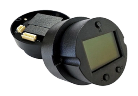
We solve the complex signal processing and HART communication challenges, allowing manufacturers to focus on mechanical design and process connections. Our level transmitter boards can support signal conditioning, 4-20mA output, HART communication, parameter configuration, fault detection, and customized integration.
ICwalk provides the process control board and circuit module rather than the complete certified level transmitter. The instrument manufacturer remains responsible for the final probe, enclosure, process connection, safety design, installation method, and compliance work. Our custom transmitter board service supports different sensor inputs, communication protocols, form factors, and application requirements.
Conclusion
A malfunctioning level transmitter circuit module can cause unstable readings, incorrect 4-20mA output, failed HART communication, slow response, or hidden diagnostic problems. Engineers should inspect the process, probe, wiring, power supply, and configuration before replacing the board.
For OEM manufacturers, the H509 capacitive level transmitter board provides an electronic foundation for custom level instruments. It supports signal processing, isolation, field adjustment, HART communication, and data recovery. At ICwalk, we focus on the internal circuit module so manufacturers can build complete level transmitters around their own mechanical, process, and safety designs.
FAQs
Q: What is a level transmitter board used for?
A: It converts sensor signals into level data, 4-20mA output, and HART communication.
Q: How do I calibrate this device?
A: Follow the manual and adjust zero, span, damping, and output using approved reference conditions.
Q: Can it display L or kg?
A: Yes, with tank geometry, density settings, and correct calibration in the complete level transmitter.


