

How Do You Perform a Loop Test on an RTD HART Temperature Transmitter?
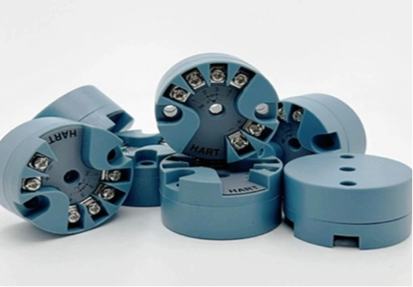
A loop test is one of the most useful checks when commissioning or maintaining an RTD HART temperature transmitter. It confirms whether the complete signal path can measure temperature, process the sensor signal, produce the correct 4-20mA output, and communicate with the control system.
For instrument manufacturers, however, a loop test is not only a field service task. It is also a way to evaluate the electronic core inside the finished instrument. The temperature transmitter board, transmitter PCBA, and process control board transmitter all influence measurement stability, output accuracy, diagnostics, and HART communication.
tại ICwalk, we provide transmitter boards for OEM instrument manufacturers. Our H3051WD temperature transmitter board is designed for RTD and thermocouple applications with isolated signal processing, 4-20mA output, and HART communication. It is an electronic module for integration, not a complete field transmitter.
What Does a Loop Test Check?
A loop test checks whether the transmitter, wiring, power supply, control-system input, and configuration work together as one measurement loop. It can reveal wiring mistakes, incorrect range settings, unstable power, damaged input circuits, or problems in the control-room display.
Before starting, engineers should read the product manual and confirm the test method approved for the finished instrument. The correct procedure may vary according to the sensor, power supply, installation area, and required safety controls.
The Main Parts of the Loop
An RTD HART temperature transmitter loop normally includes:
- An RTD sensor such as PT50, PT100, PT500, or PT1000
- The temperature transmitter board or transmitter PCBA
- A two-wire power and signal loop
- A control-system input or loop display
- A HART configuration tool or handheld communicator
- Test equipment for current, resistance, or temperature simulation
The H3051WD module supports standard RTD inputs, several thermocouple types, and millivolt or resistance signals. Its output combines a 4-20mA analog signal with HART digital communication in a two-wire system.
Why the Transmitter Board Matters
The sensor only produces an electrical response. The temperature transmitter board converts that response into a usable engineering value. It handles signal conditioning, compensation, linearization, damping, diagnostics, and output control.
If the board has unstable references, damaged input protection, incorrect sensor settings, or poor isolation, the loop test may fail even when the RTD itself is healthy. This is why OEMs should test the transmitter PCBA together with the intended sensor and wiring rather than treating the board as an isolated component.
How to Prepare for an RTD Loop Test
Good preparation makes the test faster and safer. A loop test should be planned before connecting a calibrator or changing parameters. In chemical, petrochemical, and energy applications, engineers must also consider hot surfaces, toxic materials, corrosive media, hazardous areas, and possible process interruption.
The final temperature transmitter must be suitable for its complete application. The board may provide isolation and reliable signal processing, but the instrument manufacturer must validate the enclosure, sensor assembly, process connection, wiring, and required certification.
Confirm the Sensor and Wiring
First, confirm the RTD type and connection method. A two-wire connection is simple but includes lead resistance. Three-wire and four-wire connections can reduce the effect of lead resistance and are often preferred when higher accuracy is required.
Check the following points:
- Sensor type and resistance curve
- Number of sensor wires
- Terminal identification
- Cable shielding and grounding
- Cable length and condition
- Connection between the sensor and circuit module
- Presence of moisture, corrosion, or loose terminals
The H3051WD product information lists support for PT50, PT100, PT500, and PT1000 sensors, together with multiple thermocouple inputs. It also provides DC1000V isolation for the signal-processing circuit and main circuit.
Confirm Power and Output Conditions
A stable power supply is essential for a correct loop test. Check the available loop voltage, load resistance, polarity, and control-system input. A weak supply or excessive load can make the output appear inaccurate even when the temperature transmitter board is working correctly.
Before testing, record:
- The configured lower range value
- The configured upper range value
- The expected current at each test point
- The damping value
- The selected sensor type
- The HART address and communication settings
How to Perform the Loop Test Step by Step
Once the sensor, wiring, power, and configuration are confirmed, the loop test can begin. The goal is to compare a known input condition with the current shown by the transmitter and the value received by the control system.
Step 1 Connect the Test Equipment
Connect the loop power supply and current measurement equipment according to the manual. If the test uses an RTD simulator, connect it to the sensor input terminals. If the test uses a real sensor, place the sensor at a stable reference temperature.
Do not change wiring in an energized hazardous-area installation unless the approved work procedure allows it. For production testing, use the correct fixture and confirm that the test current will not damage the transmitter PCBA.
Step 2 Check the Zero and Span Points
Apply or simulate the lower temperature value. For example, if the configured range is 0°C to 200°C, the lower point should normally produce approximately 4mA, while the upper point should produce approximately 20mA.
Then test one or more intermediate points. A useful sequence may include:
- 0% of range
- 25% of range
- 50% of range
- 75% of range
- 100% of range
The exact acceptance limits should come from the finished instrument specification. A board may have a strong published accuracy, but the complete system also includes the RTD, wiring, enclosure temperature, calibration reference, and installation conditions.
Step 3 Compare the Local and Control-Room Values
Read the value from the transmitter display, if fitted. Compare it with the HART value and the control-system value. All three should agree within the expected tolerance after allowing for damping and update time.
The H3051WD supports a data refresh rate of 2Hz and adjustable damping from 0 to 32 seconds. A high damping value can make the output appear slow during a loop test, even when the measurement is correct.
Step 4 Test HART Communication
Connect a compatible HART tool or a HART 375 communicator and check whether it can read the primary temperature variable, output current, sensor type, range, damping, and diagnostic information.
HART communication is especially helpful when an instrument appears to have a correct 4-20mA output but an incorrect parameter. It can also show whether the problem is located in the sensor input, transmitter board, loop wiring, or control-system configuration.
Step 5 Record the Results
A professional loop test should produce a record. Include the test date, instrument number, sensor type, range, test points, measured current, displayed temperature, HART data, and final result.
For OEM production, repeatable records are valuable. They help identify differences between batches and provide traceability when a customer reports a field problem. ICwalk supports configuration and calibration workflows for transmitter boards, helping manufacturers prepare consistent instruments for different applications.
How to Calibrate This Device Correctly
Many engineers ask how to calibrate this device after a loop test shows a small error. Calibration should begin only after wiring, sensor selection, power supply, and measurement references have been checked.
The general process is:
- Confirm the actual reference temperature.
- Verify the selected RTD type.
- Check the lower and upper range values.
- Apply known temperature points.
- Compare the measured value with the reference.
- Adjust the required sensor or output parameters.
- Repeat the test at several points.
- Save the configuration and record the result.
Calibration of the board alone does not prove the accuracy of the complete temperature transmitter. The final instrument should be tested with its actual RTD, wiring, enclosure, display, and operating environment.
Common Loop Test Problems
A failed loop test does not always mean the transmitter board is defective. Engineers should separate sensor faults, installation faults, configuration faults, and circuit faults before replacing a module.
Typical symptoms include:
- 0mA output caused by incorrect wiring or loss of loop power
- A fixed high or low output caused by sensor failure or input-range error
- Slow response caused by excessive damping
- Wrong temperature caused by selecting the wrong RTD type
- HART communication failure caused by loop conditions or wiring
- Intermittent readings caused by moisture, vibration, or loose terminals
In applications involving corrosive or toxic process media, the field transmitter may also be affected by sensor insulation damage, heat transfer problems, or an unsuitable thermowell. The electronics should be inspected together with the complete installation.
Why Instrument Manufacturers Choose ICwalk Boards
Instrument manufacturers may already have their own sensor assembly, housing, display, process connection, and application design. What they need is a dependable electronic core that can process RTD signals and communicate with plant control systems.
At ICwalk, we solve the complex signal-processing and HART communication challenges inside the instrument. Our temperature transmitter boards can support RTD and thermocouple inputs, isolated signal processing, 4-20mA output, HART communication, parameter configuration, and application-specific adaptation.
This allows manufacturers to focus on mechanical design, process connections, enclosure protection, and final product certification. Our temperature transmitter board category includes H3051WD, H649WD, and H648WD solutions for different installation and integration requirements.
For chemical, petrochemical, high-temperature, corrosive, toxic, or potentially flammable applications, the completed field transmitter must be assessed as a complete system. ICwalk supplies the process control board and electronic module, while the instrument manufacturer remains responsible for final safety and compliance validation.
Kết luận
A loop test confirms more than the value shown on a display. It checks the RTD sensor, wiring, power supply, transmitter board, 4-20mA output, HART communication, and control-system response as one complete path. When the test is performed with a clear manual and reliable reference equipment, faults become easier to locate.
The H3051WD temperature transmitter board gives OEM manufacturers an electronic foundation for RTD and HART temperature instruments. It supports isolated signal processing, configurable parameters, 4-20mA output, and remote communication. At ICwalk, we help manufacturers develop the inner electronics while they control the sensor assembly, mechanical design, process connection, and final certification.
FAQs
Hỏi: What current should an RTD loop show at 0%?
A: Approximately 4mA, depending on the configured range and calibration tolerance.
Hỏi: Can HART communication change the 4-20mA output?
A: No. HART data is superimposed on the analog signal.
Hỏi: Can a loop test verify liters or kilograms?
A: No. RTD transmitters measure temperature; liters or kilograms require separate process calculations.


