

Pressure Transmitter vs Transmitter Board Which Should Chemical Plants Check First in 2026?
In chemical plants, a pressure reading can influence pump protection, tank level calculation, pipeline control, batch consistency, and safety alarms. When a reading becomes unstable, maintenance teams often focus on the complete pressure transmitter first. That is reasonable, but it can miss the electronic source of the problem.
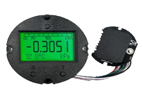
A complete pressure transmitter includes the pressure sensor, housing, process connection, sealing parts, wiring, display, and internal electronics. The pressure transmitter board is the electronic core inside it. At ICwalk, we provide this core for instrument manufacturers. Our H3051 intelligent pressure transmitter board helps OEM teams build their own field transmitter products around suitable mechanical structures and process connections.
Why Chemical Plants Need to Check More Than the Housing
Chemical and petrochemical sites place heavy demands on measurement equipment. Corrosive liquids, toxic media, steam, vibration, high temperatures, electrical noise, and long cable runs can all affect pressure data. In flammable or explosive locations, the finished instrument also needs an appropriate protection concept and certification.
The pressure transmitter board cannot replace proper wetted materials, diaphragm seals, enclosure protection, or hazardous-area engineering. However, it strongly affects how the sensor signal is processed after it enters the instrument. A weak circuit module can produce false alarms, slow response, unstable current output, or difficult maintenance work.
The Complete Pressure Transmitter Handles the Process Connection
The complete pressure transmitter is responsible for meeting the physical demands of the application. Its sensor and process connection must match the pressure range, medium, temperature, and installation method. For corrosive liquid service, the wetted materials and sealing design need careful review. For toxic media, safe maintenance access and leak prevention also matter.
Plant engineers should inspect the complete instrument first when they see visible damage, leaking seals, blocked impulse lines, condensation, or abnormal process conditions. A pressure transmitter board cannot correct a damaged sensor diaphragm or a poor installation location. The full measuring loop must be considered before replacing components.
The Pressure Transmitter Board Handles the Measurement Signal
Once the sensor produces an electrical signal, the pressure transmitter board takes over. It acts as a Sensor Signal Conditioning Board, converting a small sensor output into useful measurement data. It can manage amplification, filtering, temperature compensation, linearization, diagnostics, and communication.
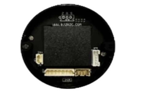
ที่ คณะกรรมการส่งความดัน H3051 is intended for instrument manufacturers that need a configurable electronic platform. It can be used with bridge-resistance pressure sensors and supports the electronics needed for pressure measurement products. The board is not a complete pressure transmitter. It is a transmitter PCBA that must be integrated with a compatible sensor, housing, display, process connection, and final compliance design.
Which Faults Should Engineers Check First
A plant does not need to treat every unstable pressure signal as a failed transmitter. The source may be the process, sensor, wiring, power loop, parameter settings, or circuit module. A structured inspection saves time and helps avoid replacing a healthy instrument.
Before opening an enclosure or changing a board, compare the indicated value with an independent pressure reference where practical. Check the application history as well. A problem that started after cleaning, a wiring change, a lightning event, or a pump replacement often points to a different cause.
Start With the Process and Installation
Many pressure faults are mechanical or process-related. A blocked impulse line can make a differential pressure reading appear lower or higher than the real condition. Vibration can affect connectors. A poorly routed cable can pick up electrical interference. Condensation inside an enclosure can create intermittent faults.
Check these points first:
- Actual process pressure and recent overpressure events
- Impulse line blockage, trapped gas, or crystallized liquid
- Diaphragm seal condition and medium compatibility
- Ambient heat near the field transmitter
- Cable shielding, grounding, and terminal tightness
- Moisture or corrosion inside the enclosure
- Power-loop voltage under normal load
For teams looking for pressure transducers with fast response times for automated packaging line control systems, installation details are especially important. Excessive damping, long impulse paths, vibration, or an unsuitable sensor range can slow the complete measurement loop before the transmitter board is even considered.
Then Check the Circuit Module and Signal Path
If the process side is stable, examine the electronics. A pressure transmitter board should receive a clean sensor signal, apply correct compensation values, and provide stable 4-20mA output. Incorrect range parameters or damaged input protection can create readings that look valid but do not match the real process.
Typical board-level checks include:
- Is the supply voltage within the approved range?
- Is the 4-20mA output stable?
- Are zero and span values correct?
- Is damping set for the real application?
- Does HART communication remain readable?
- Are temperature compensation values valid?
- Is the board protected from moisture and interference?
- Has stored configuration data been retained after power loss?
A reliable process control board transmitter design needs more than a high-resolution converter. It also needs sensible filtering, stable reference circuits, protected inputs, and clear fault behavior. That is why a transmitter PCBA should be selected as part of the complete instrument design, not as an afterthought.
Why HART Communication Changes Maintenance Work
The 4-20mA loop remains widely used because it is simple and dependable. Yet plant teams often need more than one current value. They need range details, configuration data, diagnostics, and a way to identify whether a problem comes from the sensor or the transmitter board.
This is where HART communication can support commissioning and maintenance. It gives technicians a channel for reading parameters while retaining the standard analog output used by many control systems.
Configuration Should Follow a Clear Manual
A board with HART communication still requires disciplined use. Technicians should not guess at damping, sensor range, output limits, or temperature compensation values. The instrument manual should explain the wiring method, parameter sequence, fault messages, and calibration limits.
When technicians ask how to calibrate this device, the correct answer depends on the finished instrument, sensor type, reference equipment, and approved procedure. A board-level adjustment alone does not prove that the complete pressure transmitter is accurate. Calibration must include the actual sensor and the required pressure points.
For field work, a HART 375 communicator or compatible configuration tool can help read and adjust device parameters. It is useful for checking whether the transmitter board range matches the sensor range, whether damping is too high, and whether a communication fault is present.
Separate Communication Faults From Measurement Faults
A communication problem does not always mean the pressure measurement is wrong. The 4-20mA output may remain stable while HART communication is interrupted by wiring resistance, poor grounding, unsuitable loop conditions, or incorrect parameters. The opposite can also happen: communication may work while the sensor signal is drifting.
This separation matters for maintenance planning. Check the analog output with a meter, review the digital configuration, and compare both results with a pressure reference. That simple sequence gives engineers a clearer view of whether the issue belongs to the process, sensor, wiring, or HART Protocol Module.
Why Instrument Manufacturers Choose ICwalk Boards
Instrument manufacturers may already have their own housing, process connections, diaphragm design, and application expertise. What they need is a dependable electronic core that can process sensor signals accurately and communicate with plant control systems. We provide pressure transmitter boards, process control boards, and configurable electronic modules for that purpose.
We solve the complex signal processing and HART communication challenges, allowing you to focus on mechanical design and process connections. Our products can support sensor matching, temperature compensation, 4-20mA output, anti-interference design, parameter configuration, and production needs. Explore our pressure transmitter board solutions และ ICwalk product range for pressure, temperature, flow, and level measurement electronics.
For petrochemical, toxic-liquid, corrosive, and potentially flammable applications, the final pressure transmitter still requires system-level engineering and certification. ICwalk provides the process control board and electronic module, while the instrument manufacturer remains responsible for the mechanical structure, enclosure protection, safety design, and compliance requirements.
A Better 2026 Inspection Sequence
For chemical plants, the first item to check is usually not only the pressure transmitter or only the transmitter board. It is the complete signal path. Start at the process connection, move through the sensor and wiring, then review the circuit module and control-system input.
This sequence helps teams find the real fault faster:
- Confirm the process condition and installation.
- Inspect the sensor, diaphragm, seals, and impulse lines.
- Check wiring, grounding, moisture, and loop power.
- Compare 4-20mA output with an independent reference.
- Review configuration values through the manual and HART tool.
- Assess the pressure transmitter board only after the external causes are clear.
ข้อสรุป
A pressure transmitter is the finished field instrument, but its transmitter board decides how the sensor signal is filtered, compensated, stored, and sent to the control system. In chemical and petrochemical applications, both layers deserve attention. The complete instrument must withstand the process environment, while the circuit module must provide stable measurement and communication.
For OEM teams, the H3051 pressure transmitter board offers an electronic foundation for custom pressure instruments. It helps support sensor signal processing, temperature compensation, HART communication, and 4-20mA output. At ICwalk, we focus on this inner electronic layer so instrument manufacturers can develop their own complete products around the right mechanical and safety design.
FAQs
คำถาม: Can a pressure transmitter board display L or kg?
A: Yes. With tank geometry and liquid density, the transmitter PCBA can support L or kg calculations.
คำถาม: Is a pressure transmitter board a complete field transmitter?
A: No. It is the electronic core inside a complete pressure transmitter.
คำถาม: How do I calibrate this device?
A: Follow the manual and calibrate the complete pressure transmitter with approved pressure reference equipment.


