

How to Minimize Errors in Thermocouple Temperature Transmitter Readings
How to Minimize Errors in Thermocouple Temperature Transmitter Readings?
In 2026, accurate temperature data remains essential in chemical processing, petrochemical production, storage tanks, power systems, and automated manufacturing. A small thermocouple error can affect product quality, energy use, alarm settings, and process safety.
Many users focus on the thermocouple itself. However, the sensor is only one part of the measurement chain. The internal temperature transmitter board must receive a weak millivolt signal, correct reference-junction changes, filter electrical noise, convert the signal into a stable output, and communicate with the control system.
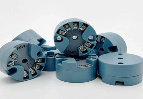
ICwalk supplies the electronic core inside the instrument rather than claiming to manufacture every complete thermocouple transmitter. Our H648WD temperature transmitter board helps instrument manufacturers develop field transmitters around their own sensor, housing, process connection, and application requirements.
Why Do Thermocouple Readings Become Inaccurate?
Thermocouples are useful because they can measure a wide temperature range and respond quickly. Yet their output is very small. The signal may be affected by reference-junction temperature, extension-wire resistance, electromagnetic interference, poor grounding, sensor aging, or incorrect wiring.
Before selecting a transmitter board, engineers should review the complete signal path. The sensor, terminal block, cable, process connection, input circuit, software, and 4-20mA output all contribute to the final reading. A board that looks accurate in a laboratory may behave differently near motors, heating equipment, switching power supplies, or long field cables.
Cold junction compensation errors
A thermocouple does not measure absolute temperature directly. It measures the difference between the measuring junction and the reference junction. If the reference-junction temperature changes, the transmitter must correct the result.
This is why cold junction compensation is a central function in a thermocouple transmitter. Without it, a stable process can appear to drift when the terminal temperature changes. The H648WD supports built-in cold junction compensation for thermocouple applications, helping the board convert the sensor signal into a more useful temperature value.
Wiring and sensor connection mistakes
Wiring errors are another common source of inaccurate readings. Reversed thermocouple wires can produce a negative response or an incorrect temperature trend. Using the wrong extension cable can also introduce an additional junction with a different thermal response.
Before commissioning, confirm:
- thermocouple type and polarity
- terminal assignment
- extension-wire material
- sensor range
- grounding method
- shield connection
- input configuration in the transmitter board
The correct steps should be documented for production and field service teams. This reduces repeated wiring mistakes during installation or sensor replacement.
How Can a Temperature Transmitter Board Reduce Measurement Errors?
The transmitter board is the measurement core of the field instrument. It does more than convert millivolts into current. A well-designed board combines sensor linearization, temperature compensation, electrical isolation, filtering, diagnostics, and communication.
For OEM manufacturers, this internal circuit module is often the most difficult part of the instrument to develop. It requires analog design, firmware, calibration tools, HART communication, EMC testing, and sensor compatibility work.
Use stable signal conditioning
A thermocouple produces a low-level signal. In a chemical plant or petrochemical facility, that signal may share space with variable-frequency drives, pumps, contactors, heating systems, and long cables. The Sensor Signal Conditioning Board must separate the useful signal from interference without making the response too slow.
A practical signal conditioning design should include:
- high-quality input amplification
- low-noise conversion
- filtering for electrical interference
- stable reference voltage
- appropriate grounding
- isolation between sensor and output circuits
- protection against overvoltage and electrostatic disturbance
ICwalk’s H648WD uses isolated temperature signal processing and supports DC1000V isolation. This can help reduce the effect of electrical interference between the sensor circuit and the main output circuit, although the complete instrument still requires system-level testing.
Apply accurate linearization
Thermocouple output is not perfectly linear. The transmitter board must use a suitable conversion method to translate the millivolt signal into a temperature value across the working range.
If the linearization table or software configuration does not match the selected thermocouple type, the transmitter may show a consistent but incorrect reading. The board should therefore support the sensor types required by the target market, such as E, J, K, N, R, S, and T thermocouples.
ICwalk’s H648WD temperature transmitter board also supports different RTD inputs, allowing one circuit platform to serve multiple temperature instrument designs. This flexibility is useful for manufacturers producing equipment for chemical tanks, ovens, pipelines, cabinets, and environmental monitoring systems.
How Should Engineers Calibrate a Thermocouple Transmitter?
Calibration should be treated as a complete process rather than a single adjustment. The reference source, sensor type, input range, output loop, communication settings, and final display must all agree.
When technicians ask how to calibrate this device, the exact procedure depends on the final housing and sensor connection. However, a typical process includes these steps:
- Confirm the thermocouple type and wiring polarity.
- Check the configured measurement range.
- Connect a calibrated temperature or millivolt source.
- Test the lower, middle, and upper points.
- Compare the board output with the reference value.
- Check the 4-20mA current loop.
- Confirm the HART variables and alarm settings.
- Record the result for traceability.
A field communicator 375 or another smart field communicator may be used when the completed field transmitter supports the necessary HART commands. A PC configuration tool can also help manufacturers complete batch calibration before shipment.
The HART Protocol Module is especially useful when maintenance teams need to review sensor type, damping, range, fault status, or output trim without removing the transmitter from service. ICwalk provides HART-compatible transmitter boards and related configuration support for OEM applications.
What Environmental Factors Affect Thermocouple Accuracy?
Temperature instruments used around toxic, corrosive, flammable, or explosive process media face more than a measurement challenge. They must also survive heat, humidity, vibration, electrical disturbance, and restricted installation space.
The circuit board may be placed inside a junction box, a DIN rail housing, a display shell, or a compact control cabinet isolated current transmitter. Each form affects heat transfer, wiring, shielding, and maintenance access.
Heat and humidity
Component drift can increase when the board operates close to its temperature limit for long periods. Moisture may also create leakage paths or corrosion if the enclosure and cable entries are not suitable.
The H648WD is specified for continuous operation from -40°C to +85°C, with relative humidity from 10% to 90% RH. The final instrument manufacturer must still verify the enclosure, sealing, condensation control, and installation conditions.
Industrial electrical interference
When temperature, pressure contact modules, and flow meter signals share one control cabinet, electrical interference can travel through power lines, grounds, or communication wiring. A process control board transmitter should therefore be tested with the surrounding equipment, not alone.
Recommended checks include:
- power interruption and restart
- output stability near switching equipment
- shield and ground behavior
- HART communication during normal operation
- sensor disconnection and overrange alarms
- response to nearby motors and contactors
These tests help reveal problems before the field transmitter reaches a chemical plant or production line.
Why Instrument Manufacturers Choose ICwalk Boards
Why Instrument Manufacturers Choose ICwalk Boards: We solve the complex signal processing and HART communication challenges, allowing you to focus on mechanical design and process connections.
ICwalk was established in 2007 and provides OEM components and smart modules for industrial automation customers in more than 50 countries. We combine signal-processing experience, automated batch calibration, product traceability, and customization support for demanding applications.
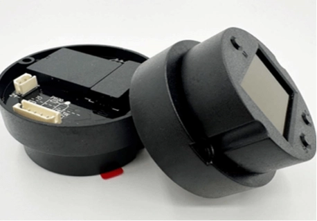
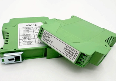
ของเรา temperature transmitter board category includes H648WD, H649WD, and H3051WD options. The H648WD is suited to junction-box installation, while the H649WD supports DIN rail installation and the H3051WD is designed for a display housing.
For manufacturers, a Transmitter PCBA can reduce development time while leaving control over the sensor, housing, display, process connection, and finished product specifications. The same design approach can also be applied to pressure, level, and flow instruments through ICwalk’s broader process control board product range.
What Should Be Checked Before Mass Production?
Before releasing a thermocouple transmitter to the market, OEM engineers should test both the board and the complete instrument.
Important checks include:
- thermocouple compatibility
- cold junction compensation
- linearization accuracy
- 4-20mA output stability
- HART communication
- isolation performance
- operating temperature
- humidity and condensation
- cable and terminal design
- enclosure heat management
- fault and alarm behavior
- calibration records
The finished field transmitter should also be tested with the intended process connection and sensor assembly. This is especially important for oil, chemical, and corrosive-liquid applications where the sensor may operate under pressure, vibration, or rapid temperature change.
ข้อสรุป
Thermocouple temperature errors rarely come from one component alone. The sensor, wiring, reference junction, signal conditioning board, software, output loop, and installation environment all influence the final reading. A reliable temperature transmitter board must provide accurate cold junction compensation, suitable linearization, electrical isolation, stable 4-20mA output, and practical HART communication. ICwalk’s H648WD gives instrument manufacturers a strong electronic core for building customized field transmitters used in chemical, petrochemical, industrial, and other demanding environments. By handling the circuit module and communication functions, we help manufacturers focus on sensor selection, mechanical design, process connections, enclosure protection, and application-specific requirements.
FAQs
คำถาม: Can a thermocouple transmitter board monitor temperature in a 5,000 L chemical tank?
A: Yes, when the sensor range, placement, materials, and board configuration match the process.
คำถาม: Can it support a 2,000 kg corrosive liquid application?
A: Yes, if the sensor, enclosure, wiring, and process materials are correctly selected.
คำถาม: Can HART help maintain a 10,000 L storage system?
A: Yes. HART supports range checks, diagnostics, configuration, and calibration access.


