

How to Diagnose and Fix Signal Drift in Process Control Board Transmitters
Signal drift in process control board transmitters stands as a typical problem. This issue can undermine measurement precision and result in unsteady process control. The transmitter output shifts away from real process conditions. As a result, the whole automation loop experiences problems. Engineers need to learn how to spot, identify, and repair this drift. Such skills prove essential for keeping system dependability and reducing stoppages. Industrial settings demand exactness and steadiness, where the function of every process control board transmitter impacts working safety and productivity directly.
What Causes Signal Drift in Process Control Board Transmitters?
Signal drift comes from various physical and working factors. These factors slowly change the transmitter output. Engineers examine environmental effects, part wear, and calibration methods. This examination helps locate the main reasons with greater precision.
Environmental Influences on Signal Stability
Environmental factors play a major role in signal drift. Changes in temperature make sensor resistance or output voltage shift in surprising ways. Moisture and dirt buildup weaken circuit protection. At the same time, electromagnetic interference (EMI) warps signal paths in active use.
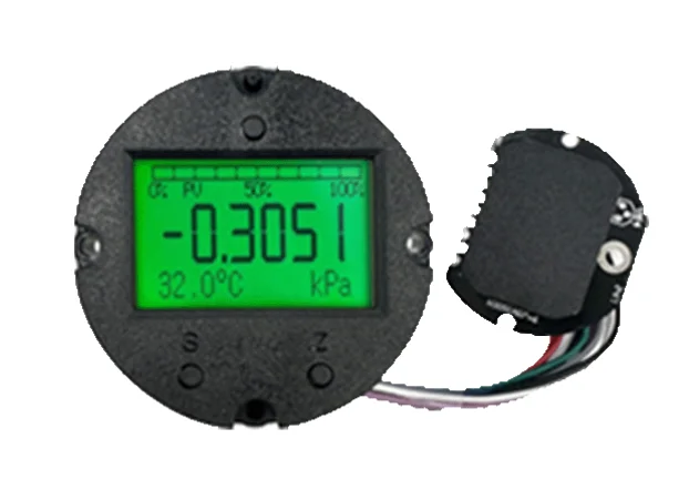
O série H3051 intelligent pressure transmitters are protected by conformal coating, which can effectively prevent damage to the electronic components caused by the external environment. This setup shows how suitable barriers and covers can lessen outside impacts, which impacts frequently cause signal drift.
Component Aging and Material Degradation
Parts like sensors, capacitors, or resistors age and drop their starting traits as time passes. Heat pressure shifts resistor levels or lowers capacitor capacity. Weak solder connections create spotty links. These links imitate signal instability.
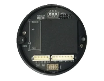
The modular design ensures high reliability, consistency, and long-term stability of the product. This idea from ICwalk’s capacitive level transmitter points out how block-based building boosts lasting signal soundness.
Calibration Errors and Improper Maintenance Practices
Improper calibration schedules or the use of non-certified instruments introduce systematic errors that accumulate gradually. Infrequent recalibration allows small deviations to persist until they become significant drifts. Maintenance routines that overlook early warning signs—such as increased damping time or irregular output—can also accelerate measurement inaccuracies.
How Can Engineers Diagnose Signal Drift Accurately?
An organized check process lets engineers tell real sensor issues from short-term disruptions. Engineers act on fixes after this separation.
Initial Inspection and Data Logging
Begin with past trend checks of transmitter outputs. Match present values to base measures or extra sensors in side-by-side setups. Search for steady shifts linked to heat patterns or machine startup steps.
Electrical Testing and Circuit Verification
Electrical testing helps verify whether drift originates from internal circuitry or external power fluctuations. Use multimeters or oscilloscopes to measure voltage stability across terminals. Inspect wiring insulation for cracks or corrosion that could introduce leakage currents.
Sensor Evaluation and Cross-checking Methods
Suspect a sensor fault. Swap the unit with a tuned base model in the same setup. Run table tests with set inputs. These tests single out whether the shift comes from the sensor part or later electronics.
What Are Effective Methods to Fix Signal Drift in Process Control Transmitters?
Spot the drift origin. Then, fix steps bring back output exactness. These steps avoid adding fresh mistakes.
Recalibration Procedures for Accurate Output Recovery
Use maker-suggested gaps for recalibration. Employ approved base tools in this process. Tune zero and range adjustments step by step. Watch live outputs for steadiness during this.
Component Replacement and Circuit Restoration Techniques
Swap worn sensors or basic parts with matches to the first specs. Rejoin loose spots with care. Use heat-managed tools to avoid burn harm.
Preventive Maintenance Strategies for Long-Term Stability
Establish periodic inspection routines focusing on high-temperature zones or areas prone to condensation. Clean circuit boards using anti-static brushes to remove dust safely. Protective coatings help resist moisture intrusion and EMI exposure over extended periods.
How Can Engineers Prevent Future Signal Drift Issues?
Preventive design plans blend strong build ideas with forecast upkeep tech. These blends bring ongoing dependability gains.
Design Optimization for Environmental Resilience
Choose parts built for broad heat spans (e.g., -40°C to +85°C). Many factory-level transmitters from ICwalk products offer this. Add barrier layers near key circuits. Barriers cut the electrical link effects between strong power lines.
Extra sense setups suit spots where key readings skip stoppages. For example, two-way magnetostrictive level transmitters give separate 4–20 mA signals. These signals add backup in vital safety uses.
Predictive Maintenance Using Digital Monitoring Tools
IoT-based checks permit far-off watch of transmitter work details. Details cover loop flow changes or inner heat shift patterns.
Summary
Signal drift in process control board transmitters breaks factory exactness. Quick fixes stop this. Outside pressures like heat jumps, old electronics, or calibration skips often cause shaky values. Use planned checks. Checks mean data records, wiring exams, and sensor reviews. Pair with aimed fixes like recalibration or part swaps. Engineers then bring back sharp work fast.
View from a field angle. ICwalk supplies pro-level electronic parts. The parts suit steady signal flow in tough process control setups. With over 16 years of expertise, we serve clients across 50+ countries. We deliver OEM parts and smart units that fit world rules like HART and PROFIBUS-PA. Our products stress dependability up front. Patented math hits ±0.1% exactness even in harsh spots. This base backs steady work in hard factory spots.
FAQ
Q: What are common signs of signal drift in a process control board transmitter?
A: Usual signs cover slow shifts from planned values in steady setups. Or, constant recalibration calls despite the same inputs. These often point to inner part wear or EMI hits.
Q: How often should a process control board transmitter be recalibrated?
A: Many factory plans do recalibration every 6–12 months. The choice depends on outside toughness. Rough heat rounds might need quicker gaps. Field test outcomes confirm this.
Q: Can protective enclosures reduce signal drift risk?
A: Yes, closed covers guard from moisture and dirt. Metal shells weaken electromagnetic interference. The interference hits analog wiring inside transmitters.
Q: When should engineers choose replacement instead of repair?
A: Check outcomes show heavy part wear. Examples include rusted links or shaky boosters. In these cases, swapping gives stronger lasting dependability. This beats ongoing quick patches.
Postos relacionados
-
Como é que os transmissores podem melhorar o controle de processos nos tratamentos de calor?
29 de maio de 2025
-
Comprehensive Guide to Selecting a High-Performance Pressure Control Board for Transmitter
May 07,2026
-
Why Temperature Transmitters Fail Under EMI Stress
May 01,2026
-
Optimizing Industrial Automation: The Critical Role of Process Control Board Transmitters
April 24,2026
-
How Do Temperature Transmitters Handle Electromagnetic Interference in Densely Packed Automation Cabinets
May 08,2026


