

How Do You Choose a Temperature Transmitter Board for Hazardous Petrochemical Applications in 2026?
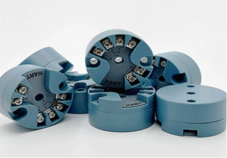
Reliable temperature measurement is critical in refineries, chemical plants, and other hazardous environments. The performance of a temperature transmitter depends not only on the sensor and enclosure, but also on the transmitter board that handles signal conversion, compensation, isolation, and communication.
At ICwalk, we focus on OEM temperature transmitter boards rather than complete field instruments. Our H648WD supports RTD and thermocouple inputs, isolated 4–20 mA output, and HART communication, making it suitable for manufacturers developing temperature instruments for corrosive, toxic, flammable, and explosive applications.
Which Temperature Transmitter Type Fits the Process?
The best electronics cannot fix a poor sensor choice. Begin with the process temperature. Consider the required accuracy, response speed, cable distance, vibration levels, and maintenance plan. In petrochemical service, the two common choices remain an RTD transmitter and a thermocouple transmitter. However, they work best under different measurement conditions.
Choose an RTD Transmitter for Stable Process Control
An rtd transmitter often provides the stronger choice for reactors, pipelines, storage tanks, heat exchangers, and dosing systems. In these areas, stable and repeatable readings matter more than an extremely high temperature limit.
Pt100 remains widely used. It offers a predictable resistance curve and good repeatability. Three-wire input stays common in industrial applications. It compensates for much of the lead resistance without the need for four conductors. Four-wire input can deliver better lead compensation when the cable runs long or the accuracy target stays tight.
The transmitter board must excite the RTD correctly. It measures small resistance changes. It corrects lead-wire effects. It linearizes the sensor curve. Finally, it converts the result into a signal that the control system can read.
Choose a Thermocouple Transmitter for High Heat
A thermocouple transmitter works better for furnaces, fired heaters, cracking units, flare-related systems, and processes with fast thermal cycles. Thermocouples cover a wider temperature range. They also react quickly. Yet their millivolt signals stay small and face more exposure to electrical noise.
The electronics require stable amplification. They need digital linearization and cold junction compensation. Sensor extension wire, polarity, grounding, and terminal temperature all affect the final result. The thermocouple itself therefore forms only one part of the complete measurement chain.
What Is Inside a Complete Temperature Transmitter?
A complete temperature transmitter normally includes a sensor, thermowell or process connection, enclosure, terminals, power and communication interface, optional display, and transmitter board. The enclosure may carry hazardous-area approvals. The board performs the measurement work. Keeping these roles separate helps OEMs source the right component. It also prevents a board from being marketed as a finished instrument.
Sensor Input and Signal Conditioning
The transmitter board receives resistance, millivolt, RTD, or thermocouple signals. It filters electrical noise. It converts the analog input into digital data. It applies sensor linearization. It also corrects known sources of error.
For an rtd transmitter, these tasks include wire-resistance compensation and accurate low-level resistance measurement. For a thermocouple transmitter, they include cold junction compensation and stable millivolt conversion. Poor input design can create unstable or drifting readings. This happens even when the sensor itself works correctly.
This area shows where a high-quality temperature transmitter becomes more than a metal housing. Its core value lies in the signal path:
- Input protection
- Analog-to-digital conversion
- Sensor compensation
- Digital processing
- Current output
- Field communication
Isolation, 4–20 mA Output, and HART Communication
Electrical isolation separates the sensor-side circuit from the main output circuit. It helps reduce problems caused by ground loops, electrical interference, and potential differences between field equipment and the control room.
However, isolation alone does not make a final instrument explosion-proof or intrinsically safe.
A hart transmitter combines a 4–20 mA analog signal with digital communication. The analog current remains useful for established control systems. The digital channel supports configuration, diagnostics, calibration, and maintenance.
For 2026 projects, this mixed approach stays practical. It works when a plant needs better device access without replacing its complete control architecture.
Why Is the H648WD a Practical Core Board?
For a junction-box or head-mounted design, we recommend our H648WD temperature transmitter board as the core product for this application.
It is an isolated transmitter board designed for RTD and thermocouple inputs. The board converts field signals into an isolated 4–20 mA output with HART communication.
Key design points include:
- Support for Pt50, Pt100, Pt200, Pt500, Pt1000, and other RTDs
- Support for common and extended thermocouple types
- Two-wire, three-wire, and four-wire RTD connections
- Internal cold junction compensation
- Millivolt and resistance measurement
- DC 1000 V electrical isolation
- DC 10–32 V power supply
- Operating temperature from −40°C to +85°C
- Compact 44 mm round format
- Output accuracy stated at 0.1%, depending on input and configured range
These features make the H648WD useful for OEMs. They develop a temperature transmitter for petrochemical skids, storage tanks, thermal process equipment, pipelines, and remote field measurement points. ICwalk publishes the detailed input ranges and accuracy conditions on the product page.
The full ICwalk temperature transmitter board range also gives instrument designers choices for different mounting and display requirements.
How Should the Board Be Built Into a Hazardous-Area Instrument?
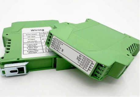
A transmitter board forms the electronic core. Yet the final instrument still requires careful electrical, mechanical, thermal, and certification work. The following design stages help engineers turn a board-level component into a dependable product. They keep component performance separate from complete-instrument approval.
Match the Electrical Design to the Field Loop
Check the sensor type, number of wires, measuring range, power supply, load resistance, cable length, grounding method, and control-system input.
Confirm that enough loop voltage remains. Account for these factors:
- Cable voltage loss
- Safety barriers
- Signal isolators
- Input resistance
- Terminal resistance
- Power supply tolerance
For thermocouples, use the correct extension cable. Keep polarity consistent. For RTDs, select two-, three-, or four-wire input. Base the choice on cable resistance and accuracy requirements.
The hart transmitter communication path should also undergo testing. Perform the test through the complete field loop, not only on a laboratory bench.
Treat Corrosion and Explosion Protection as System Tasks
Toxic or corrosive liquid should never touch the transmitter board. The process-facing parts include the sensor sheath, thermowell, seal, fitting, and process connection. Their materials must match the chemical composition, pressure, temperature, and corrosion level of the application.
The board normally sits inside a protected enclosure. Depending on the final design, the instrument manufacturer may also need these elements:
- Protective coating against humidity and corrosive gases
- Surge and reverse-polarity protection
- Suitable terminal spacing
- Grounding and shielding
- Vibration-resistant mounting
- Potting or encapsulation
- Thermal management
In flammable or explosive areas, the final assembler must select the required protection method. This may involve an approved explosion-proof enclosure. It can also mean an intrinsically safe circuit used with suitable barriers.
The H648WD’s DC 1000 V isolation supports a robust signal design. Still, it does not replace hazardous-area certification. The complete temperature transmitter must receive testing and approval. Follow the standards required by its destination market and hazardous zone.
When Do Other ICwalk Boards Fit Better?
Our H648WD suits compact junction-box designs. Yet another form factor may fit the instrument architecture better.
- O H649WD DIN-rail transmitter boardoffers a practical choice. It works when signal conversion sits inside a control cabinet rather than in the field head. It supports RTD and thermocouple inputs, isolated 4–20 mA output, and HART communication.
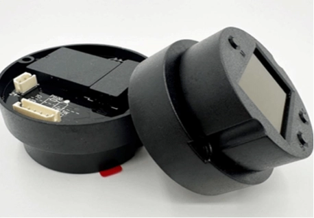
- O H3051WD temperature transmitter boardtargets a larger 3051-style housing. It fits display-oriented instrument designs.
- OEMs needing different sensor inputs, measurement ranges, compensation parameters, mounting structures, or communication functions can discuss the project through ICwalk technical contact.
At ICwalk, we focus on transmitter board design, signal processing, calibration support, and OEM integration. Our products serve as core components for instrument builders. They are not presented as complete process-ready temperature transmitters.
What Should Buyers Check in 2026?
Before approving a transmitter board, prepare a requirement sheet. It should cover the complete measurement chain:
- RTD, thermocouple, resistance, or millivolt input
- Minimum and maximum calibrated range
- Required total loop accuracy
- Two-, three-, or four-wire RTD connection
- Cold junction compensation method
- Isolation voltage
- Expected electrical interference
- 4–20 mA load budget
- HART communication requirements
- Board diameter and mounting holes
- Terminal and enclosure clearance
- Ambient temperature and humidity
- Vibration conditions
- Protective coating requirements
- Final hazardous-area certification route
- Calibration and traceability
- Field configuration and maintenance access
Do not compare products by one accuracy figure alone. The sensor error, board conversion error, lead resistance, cold junction error, installation method, and calibration range all add to the final measurement result.
Conclusão
Choosing a temperature transmitter for petrochemical service should start with the process, sensor, and safety method. It then moves inward to the electronics. RTDs suit stable and accurate process control. Thermocouples cover higher temperatures and faster changes. In both cases, the transmitter board performs the demanding work of signal conversion, compensation, isolation, and communication.
For compact junction-box instruments, the ICwalk H648WD provides broad RTD and thermocouple support. It delivers isolated 4–20 mA output, HART communication, and a practical round form factor. It remains a board-level component, not a finished hazardous-area transmitter. OEMs must combine it with suitable process-facing parts, housing, protection circuits, and certification. This clear division produces safer instruments. It also creates clearer specifications and fewer integration problems.
FAQs
Q: Is a transmitter board a complete temperature transmitter?
A: No. It is the electronic core used inside a complete temperature transmitter.
Q: Can the H648WD support a Pt100 rtd transmitter design?
A: Yes. It supports Pt100 with two-, three-, or four-wire connections.
Q: Does isolation make a hart transmitter explosion-proof?
A: No. Explosion protection depends on the complete certified instrument design.


