

How to Connect Field Communicators to Transmitters
Field communicators play a key role in today’s process automation. They help engineers set up, adjust, and fix transmitters right in the field. By 2026, their importance will grow further with digital tools and smart checks. This guide explains how to link a field communicator to a transmitter in a simple and secure way.

Field Communicators and Transmitters
Field communicators serve as the main support for current tool upkeep. Before you make links, it helps to grasp their roles. You also need to know how they work with transmitters.
Overview of Field Communicators
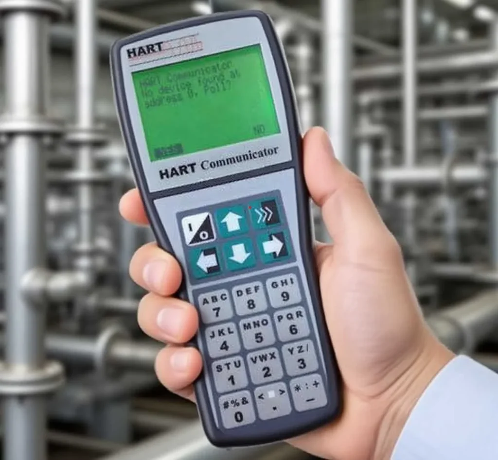
Field Communicators are portable gadgets built for setting up, tuning, and fixing smart transmitters. They use common industrial links like HART, FOUNDATION Fieldbus, or Profibus PA. Their easy-to-carry design lets engineers do checks right at the setup spot. This means no need to take apart the gear.
The H475 Field Communicator works with HART fieldbus tools. It allows setup or fixes in the field. It uses EDDL tech that supports talks with many devices from different makers. The device has a color LCD touchscreen. It includes a battery pack that recharges. Plus, it features a CORTEX-M3 CPU and strong fieldbus parts for steady work in tough factory settings.
Types of Transmitters Used in Process Industries
Transmitters turn real-world readings—like pressure, temperature, flow, or level—into standard electric signals (4–20 mA or digital). Smart ones also handle digital talks for far-off setups and checks. For good results, the communicator’s link method (such as HART) must match the transmitter’s method.
ICwalk provides several transmitter kinds. These include H3051 Pressure Transmitter, H648WD Temperature Transmitter, and H760 Ultrasonic Level Transmitter. Each one backs HART talks for smooth pairing with tools like the H475.
Preparing for the Connection Process
Before you join a field communicator to a transmitter circuit, getting ready ensures safety and precision in setup.
Checking Compatibility Between Devices
Make sure both tools use the same link type—often HART for basic analog circuits. Check the software versions on each item. This way, device guides (DD files) fit the newest rules. Makers release fresh DD/EDD files often. These boost, pairing with new types. Downloading them on a regular basis avoids link problems.
Look over each item’s guide with care. Some transmitters need certain resistor levels or wire directions during prep.
Gathering Necessary Tools and Equipment
You need basic items like link wires with clip ends or plug tips, resistors (usually 250 Ω), a steady power source (12–32 V DC), a multimeter for checks, and copies of user guides. Good-quality wires cut down on noise risks during link tests.
Establishing Physical Connections
With matching confirmed and items gathered, you must set up the wiring correctly. This avoids signal drops or harm to tools.
Wiring Setup for HART Communication
Link the communicator alongside the transmitter’s circuit wires. Do this at connection points or test spots on the control system’s input part. Keep the full circuit resistance between 230 and 1100 ohms. That range helps both tools spot frequency changes well. Always verify wire directions when joining at transmitter ends. Wrong directions might stop the link from starting.
Powering Up the Loop Safely
Confirm the power level fits the transmitter’s needs before turning it on. For example, ICwalk’s H760 Ultrasonic Level Transmitter runs on 12–32 V DC. Tighten all connection screws firmly. This prevents spotty contacts during tests. Use lockout/tagout steps when handling live process spots or risky areas.
Configuring Communication Settings on the Field Communicator
Once powered safely, setup starts with link startup. Then, it moves to tweaking settings in the communicator’s display.
Initiating Device Detection and Identification
Turn on the communicator. Pick “HART Mode.” Let it scan on its own until the linked tools show on the screen. Verify the right transmitter label or spot matches your records. Then, go ahead with setup tweaks.
The H475 Field Communicator scans spot 0 tools up to one kilometer away. It uses standard load resistance of 250–600 ohms. This suits most factory setups that need long-reach work.
Accessing Transmitter Parameters for Configuration
Move through menu choices. These cover reading range settings (zero/span), unit types (Pa, °C), steadying time lengths, alert bounds, and output styles. Change them to fit the process needs. For instance, set high/low pressure bounds on an H3051T3 Pressure Transmitter. Or, adjust temperature tune points on an H648WD unit. Save the updates. They will show in both the communicator’s storage and the transmitter’s software at the same time.

Performing Calibration and Verification Tasks
Calibration keeps reading accuracy after link setup or change tweaks.
Conducting Zero and Span Adjustments
Use known test inputs (like a pressure tuner or heat bath). Match them to zero/span spots in the reading range. Pick communicator tools such as “Zero Trim” or “Sensor Trim” if errors go beyond allowed limits. Note calibration outcomes in upkeep records. Follow ISO-based steps. ICwalk’s auto-made systems provide steady accuracy of ±0.1%.
Verifying Signal Integrity After Configuration
Watch current process readings on the communicator’s live view. At the same time, check circuit current steadiness (4–20 mA). Look at the check menus for warnings on sensor breaks or wire problems.
Troubleshooting Common Connection Issues
If the link fails even with proper wiring, steady checks help spot main problems fast.
Communication Failure Diagnosis Steps
Examine wire flow with a multimeter. Confirm resistance stays in the normal range (~250 Ω). Make sure no other working communicators use the same circuit at once. This avoids clashes. If problems continue, reboot both tools. It resets talk conflicts between spots.
Handling Protocol-Specific Problems
For HART Devices:
Keep circuit resistance at least above 230 ohms. Low levels stop proper FSK change spotting by tools like H475E units.
For Fieldbus Devices:
Verify end caps are in place at both sides of the network lines. Without them, bounce noise harms signal quality over far stretches.
For Profibus Devices:
Check speed rates match across all points. Different rates lead to timing errors. This blocks agreement signals from transmitters.
Maintaining Reliable Communication Practices in 2026 Systems
As Industry 4.0 setups grow with IoT sensors tied to main watch platforms, keeping solid link habits matters for lasting output.
Importance of Regular Firmware Updates
Update field communicators with maker-provided DD/EDD sets. They back new transmitter types like magnetostrictive level sensors or electromagnetic flowmeters from ICwalk since 2024. Updates widen pairing options. They also improve check details against new safety rules in factory networks.
Implementing Safe Maintenance Procedures
Stick to firm lockout/tagout actions before unplugging tools from powered systems in upkeep rounds. Record each setup change in asset tracking software. This ensures clear paths for reviews. It matches ICwalk’s auto-tracking systems. They offer simple quality checks via electronic code following.
Leveraging Digital Transformation Tools
New setups let handheld communicators link to phone/cloud apps. This gives techs far-off access through Wi-Fi links or Bluetooth parts built into transmitters. Smart sensor-based ahead checks can predict part wear patterns. They cut stop times a lot. Plus, they improve spare part plans based on real gear health data.
FAQ
Q: What is required before connecting a field communicator to a transmitter?
A: Verify both use identical protocols such as HART; check firmware versions match the latest DD files; ensure power supply ranges align with product datasheet values typically between 12–32V DC, depending on model type, like ultrasonic or pressure series from ICwalk.
Q: How can incorrect wiring affect field communicator performance?
A: Improper polarity or low loop resistance below 230 ohms can block frequency shift keying signals used by communicators, leading to failed detection attempts even though voltage appears normal across terminals.
Q: Which ICwalk transmitters are compatible with standard field communicators?
A: Models supporting two-wire HART output, including H3051 Pressure Transmitter series, H648WD Temperature modules, and H760 Ultrasonic Level units, communicate seamlessly using recognized industry-standard protocols tested under ISO-compliant calibration rigs at ICwalk facilities.
Q: How often should calibration be performed after initial setup?
A: Typically once per year under stable environmental conditions; however, high-vibration sites may require semiannual checks using zero/span verification functions built into handheld communicators, ensuring ±0.1% linearity retention across the full scale range.
Q: What safety measures should technicians observe when connecting field communicators to transmitters?
A: Always follow lockout/tagout procedures before touching energized loops; wear antistatic gloves where necessary; confirm hazardous area certifications if working near explosive media, since many ICwalk transmitters feature optional Exia II B T4/T5/T6 Ga explosion-proof ratings suitable for petrochemical zones.
Related Posts
-
Comprehensive Guide to Selecting a High-Performance Pressure Control Board for Transmitter
May 07,2026
-
How Do Temperature Transmitters Handle Electromagnetic Interference in Densely Packed Automation Cabinets
May 08,2026
-
How to Connect Field Communicators to Transmitters
April 30,2026
-
Why Temperature Transmitters Fail Under EMI Stress
May 01,2026
-
Optimizing Industrial Automation: The Critical Role of Process Control Board Transmitters
April 24,2026


