

How Can a Faulty Level Transmitter Circuit Module Impact Performance?
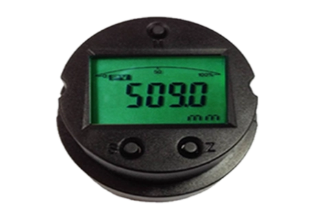
A level measurement problem rarely starts with the display. In many tanks, vessels, and chemical process lines, the first visible sign may be an unstable reading, an unexpected alarm, or a 4-20 mA output that no longer matches the real liquid condition. Behind those symptoms, the issue may sit inside the level transmitter board.
For instrument manufacturers serving petrochemical, corrosive-liquid, toxic-media, and potentially flammable applications, the complete level transmitter requires careful mechanical and safety design. However, the circuit module remains the measurement core. It receives the sensor signal, filters interference, calculates level data, manages diagnostics, and sends usable information to the control system.
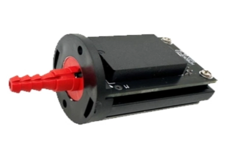
At ICwalk, we supply transmitter boards for instrument manufacturers. Our level transmitter board range supports OEM development, including capacitance, magnetostrictive, ultrasonic, and other level measurement designs. This article focuses on the H509 capacitive level transmitter board and explains how a faulty circuit module can affect the performance of the finished instrument.
Why the Circuit Module Matters in Level Measurement
A complete capacitive level transmitter may include a probe, process connection, enclosure, cable assembly, display, power supply, and transmitter board. The board is not the finished transmitter. Still, it is the part that turns changes in capacitance into a stable measurement that operators can use.
A reliable transmitter board must perform several connected tasks:
- Excite or evaluate the sensing element correctly.
- Capture weak and changing sensor signals.
- Remove electrical noise from pumps, drives, motors, and long cables.
- Apply calibration parameters for the selected probe and vessel.
- Convert the result into 4-20 mA, digital communication, alarms, or local display data.
- Retain settings and report fault conditions when the sensor signal becomes abnormal.
The H509 board can serve as the electronic core of a capacitance level gauge. For an OEM, this creates a practical division of work. The instrument manufacturer can focus on probe design, wetted materials, tank connection, enclosure, and the complete approval path. Meanwhile, our process control board handles the complex measurement and communication work inside the instrument.
Where Faults Enter a Level Transmitter Circuit Module
A circuit module may fail suddenly after a surge, but many field issues develop slowly. Humidity, unstable power, poor grounding, contamination, sensor mismatch, cable damage, and aging components can all change how the transmitter board reads the sensor. These problems are especially important in plants where process conditions are demanding and incorrect level data can interrupt production or create safety concerns.
Signal Conditioning Drift Can Create False Level Changes
Capacitive level measurement depends on detecting changes in capacitance between the probe and its reference point. The signal can be influenced by cable capacitance, coating on the probe, temperature variation, tank geometry, and the electrical properties of the process medium. The Sensor Signal Conditioning Board must separate a meaningful change from normal electrical disturbance.
When analog components drift or the input stage is damaged, the output may slowly move away from the actual process level. Operators may see a tank that appears to fill or empty without a real process change. This issue is difficult because the reading can still look believable.
Common signs include:
- The displayed level changes when nearby equipment starts.
- The 4-20 mA output does not return to its normal zero point.
- Recalibration works briefly, then the measurement drifts again.
- Level values become unstable at a fixed liquid level.
- The instrument reacts differently after temperature changes.
A sound level transmitter board uses careful signal filtering, stable reference circuits, and appropriate calibration handling. The board must also match the selected sensor. A capable circuit module cannot remove every error caused by poor probe selection, unsuitable installation, or process buildup.
Output and Communication Faults Can Hide the Real Process Condition
The measurement may be correct inside the transmitter, yet the control system can still receive the wrong signal. A damaged 4-20mA Transmitter Board, loose terminal, poor loop-power condition, or communication fault can cause this gap between the internal calculation and the displayed plant value.
In modern instrumentation, the transmitter board may need to provide analog output, pulse functions, alarms, or digital data through a HART Protocol Module. These functions add value, but they also require reliable isolation, stable power, correct wiring, and disciplined configuration.
For example, a process control board transmitter assembly may send a stable current signal while a digital setting is incorrect. In another case, the HART module may communicate intermittently because of wiring resistance, grounding conditions, or an unsuitable host configuration. The result is wasted maintenance time because the team may inspect the probe first while the fault is actually on the electronics side.
What a Faulty Transmitter Board Can Do to Plant Performance
A faulty circuit module does more than create an inconvenient display value. In a petrochemical or chemical application, level information may support inventory management, high-level alarms, pump control, batch sequencing, overflow prevention, and material transfer. The impact depends on how the final instrument is used.
Incorrect Readings Can Disrupt Process Control
When the transmitter board reports a higher level than the real tank level, operators may stop filling too early. When it reports a lower level, the system may keep filling longer than intended. Either situation can affect production balance, batch quality, and available storage capacity.
For toxic or corrosive liquids, incorrect information may also lead to unnecessary manual checks near hazardous process equipment. That adds exposure for maintenance personnel and increases downtime. A stable level transmitter board helps the finished instrument provide data that operators can trust, but it must be calibrated with the actual probe and application conditions.
Poor Diagnostics Can Turn a Small Fault Into a Larger Issue
A basic circuit module may only send a number. A stronger design also helps reveal when that number is questionable. Fault detection is important when the sensor is disconnected, the cable is damaged, the probe is heavily coated, or the process condition is outside the expected range.
Instrument manufacturers should define fault behavior early in development. The transmitter board should have clear rules for output limits, alarm conditions, parameter recovery, and restart behavior after a power interruption. These details should appear in the instrument manual, so installation and maintenance teams know what a fault state means.
Without clear diagnostics, a faulty board can produce a normal-looking value while the process has changed. In a high-risk application, that is often worse than a visible alarm.
Unstable Communication Slows Maintenance Decisions
A stable 4-20 mA loop remains important because it is simple, widely used, and suitable for many industrial environments. Yet commissioning and maintenance are easier when technicians can access configuration and diagnostic information through a HART module.
If the communication section is faulty, teams may lose access to calibration settings, device status, or range data. They may need to remove the instrument from service just to confirm a basic configuration issue. For OEMs, integrating the right transmitter PCBA can reduce this burden by giving the final instrument a consistent communication foundation.
Why Instrument Manufacturers Choose ICwalk Boards
Instrument manufacturers need room to build a differentiated product. They may have their own probe structure, enclosure design, display style, process connection, or market-specific approval plan. What they often do not want to recreate from the beginning is the analog signal processing and communication architecture.
We solve the complex signal processing and HART communication challenges, allowing you to focus on mechanical design and process connections.
With ICwalk, OEM teams can discuss board selection and customization around their intended measurement principle. For the H509 capacitive level transmitter board, the key conversation is not simply whether the board fits inside an enclosure. It is whether the board, probe, cable, power method, output type, and calibration method work together as one instrument.
Our support can cover practical needs such as output selection, communication requirements, parameter behavior, display integration, and sensor matching. The final manufacturer remains responsible for validating the complete transmitter in its real application, including corrosion resistance, ingress protection, hazardous-area design, and certification where required.
A Practical Inspection Guide for Suspected Board Faults
Before replacing a level transmitter board, maintenance teams should separate sensor, wiring, power, and circuit issues. A methodical check can prevent unnecessary replacement and reveal the real source of the problem.
Start with these steps:
- Compare the indicated level with an independent tank-level check.
- Inspect power supply voltage and loop current under normal load.
- Check terminals, shield grounding, cable damage, and moisture entry.
- Review whether the problem began after a surge, maintenance event, or process change.
- Confirm the probe is compatible with the medium and free from heavy coating.
- Compare current calibration values with the instrument manual.
- Check whether the analog output and HART communication show the same condition.
- Test the board with a known-good sensor or approved simulation method where available.
When the board is suspected, provide the sensor type, capacitance range, cable length, power supply, output requirement, process medium, and fault description to our technical team. That information makes it easier to determine whether the issue relates to the circuit module, application conditions, or the overall transmitter design.
Conclusion
A capacitive level transmitter is only as dependable as the signal path between its probe and the control system. The level transmitter board is central to that path. It conditions the sensor signal, supports calibration, handles outputs, and helps expose abnormal conditions before they become misleading process data.
For OEMs building instruments for corrosive, toxic, or demanding industrial services, the H509 capacitive level transmitter board provides a focused electronics foundation. It should be integrated with the right probe, enclosure, process connection, and validation program. At ICwalk, we help instrument manufacturers build that foundation while they retain control of the complete transmitter design and its application-specific requirements.
FAQs
Q: Can a level transmitter board directly display liters or kilograms?
A: It can support OEM scaling, while tank geometry and liquid density determine liters or kilograms.
Q: Is the H509 capacitive level transmitter board a complete hazardous-area transmitter?
A: No. The finished instrument requires its own protection design, testing, certification, and installation review.
Q: When should a transmitter board be recalibrated?
A: Recalibrate after probe replacement, major process changes, abnormal drift, or values that conflict with manual level checks.


