

3-Wire vs 4-Wire RTD Input: What Your Transmitter Electronics Must Handle
RTD Input Design for Temperature Transmitter Boards: 3-Wire vs 4-Wire RTD Guide
What is an RTD Sensor in Industrial Temperature Measurement
A Resistance Temperature Detector (RTD) serves as an accurate sensor for temperature. It gauges temperature by linking the resistance within the RTD element to the actual temperature levels. Builders typically select platinum, nickel, or copper as the main materials. Yet, platinum remains the top choice due to its strong straight-line response and reliable performance. The principle of operation is straightforward — as temperature increases, the electrical resistance of the metal element rises predictably.
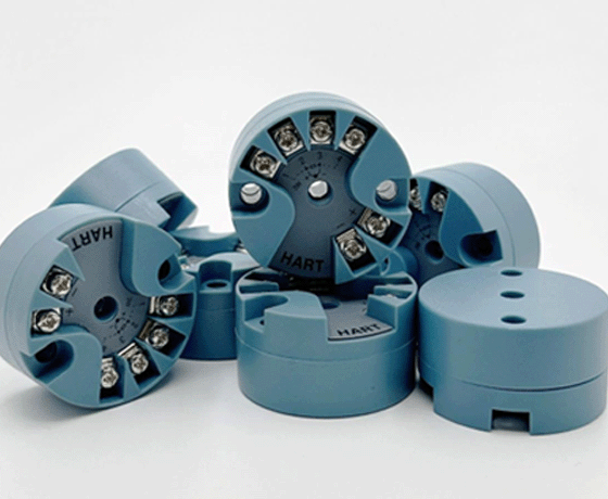
RTDs are widely used in industrial automation, oil and gas, HVAC systems, and process control because of their high accuracy, repeatability, and long-term stability. For example, the H648WD series of isolated temperature transmitters is engineered to linearize signals from ThermoCouples (TC) or Resistance Temperature Detectors (RTD) in the field and convert them into a linear 4–20mA current isolated output that is proportional to temperature. This demonstrates how modern transmitter boards integrate RTD inputs for precise measurement.
3-Wire RTD Input vs 4-Wire RTD Input in Temperature Transmitter Boards
3-Wire RTD Input Configuration for Industrial Transmitters
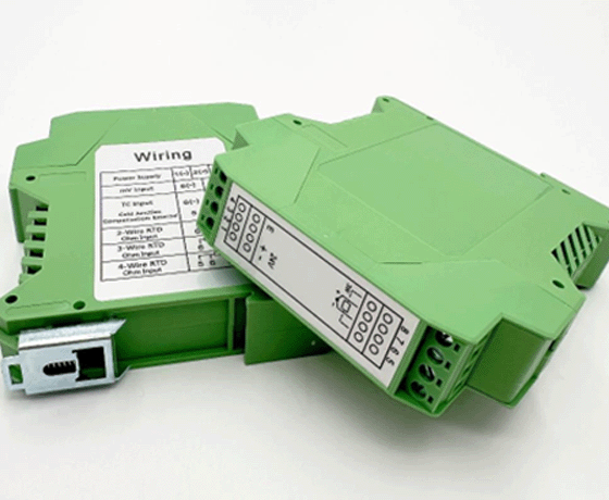
A 3-wire RTD configuration uses three leads — two connected on one side of the sensing element and one on the other. This setup compensates for lead wire resistance by assuming both leads have equal resistance. The transmitter electronics subtract this value from the total measured resistance to estimate the true sensor resistance.
This configuration is widely adopted in industrial environments due to its balance between cost and accuracy. It’s particularly effective when using short cable runs or when moderate accuracy is acceptable. Many OEMs prefer it because it reduces wiring complexity while maintaining reliable performance.
4-Wire RTD Input for High-Accuracy Temperature Transmitters
The 4-wire configuration provides the highest measurement accuracy by using two wires to carry excitation current and two separate wires to sense voltage across the sensor element. This eliminates errors caused by lead wire resistance since no current flows through the sensing leads.
High-end transmitters like the H3051WD Intelligent Temperature Transmitters are specifically designed for high-performance HART protocol temperature measurement applications. These devices support PT100 and other RTDs with both 3-wire and 4-wire configurations, offering flexibility between cost-effective and precision setups.
Applications requiring laboratory-grade precision or long-distance sensor installations typically use 4-wire RTDs to ensure signal integrity under varying environmental conditions.
3-Wire vs 4-Wire RTD Accuracy and Cost Comparison
In real-world installations, a 3-wire system can achieve ±0.2°C accuracy under ideal conditions but may degrade with longer cables or unbalanced wiring resistances. A 4-wire system maintains near-ideal compensation regardless of cable length. However, it comes with higher installation costs due to additional wiring.
For OEM board design, choosing between these configurations depends on application needs. The trade-off lies between cost efficiency and measurement precision — critical factors in designing scalable transmitter solutions such as ICwalk’s rtd transmitter pcb boards.
Temperature Transmitter Board Function in RTD Signal Conversion
How RTD Transmitter Electronics Convert Resistance to 4–20mA Signals
Temperature transmitter boards convert small resistance changes from an RTD into standardized analog signals like 4–20mA or digital HART outputs. The process involves stable excitation current generation, signal amplification, filtering, analog-to-digital conversion (ADC), and linearization algorithms.
The H648WD transmitter offers a power supply range of DC10–32V with an output of 4–20mA DC with HART communication superimposed. Such designs ensure compatibility with distributed control systems while maintaining low noise levels during transmission.
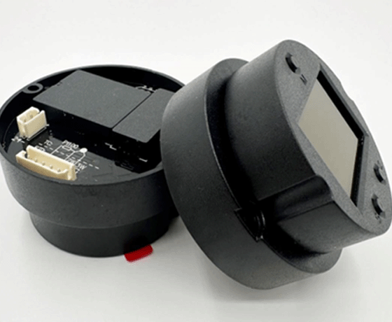
Why RTD Transmitter PCBs Affect Measurement Accuracy and Stability
PCB layout plays a decisive role in minimizing noise pickup and thermal drift. Poor grounding or trace routing can introduce microvolt-level errors that translate into significant temperature deviations. Using precision resistors, low-noise op-amps, and stable reference sources ensures consistent performance even under harsh industrial conditions.
ICwalk emphasizes this through Smart Production Lines: Fully automated batch calibration (e.g., HGZ32U rigs) and real-time fault analytics guarantee ISO-compliant quality. Such automation ensures every RTD transmitter PCB maintains repeatable calibration integrity across production batches.
Common RTD Input Challenges in Industrial Temperature Transmitter Design
Wire Resistance Error in 3-Wire RTD Systems
Unbalanced lead resistances can cause offset errors if one lead has a higher resistance due to corrosion or poor connections. Over long distances, even small differences can accumulate into noticeable inaccuracies affecting process control reliability.
Accuracy Limitations and Wiring Complexity in 4-Wire RTD Systems
While offering superior accuracy, a 4-wire system requires more complex wiring harnesses and connectors. In some field installations where space or conduit size is limited, this can increase installation time and cost.
RTD Transmitter PCB Design for 3-Wire and 4-Wire Inputs
Key PCB Design Factors for RTD Transmitter Boards
Designing an RTD transmitter PCB requires attention to trace impedance matching, shielding against electromagnetic interference (EMI), and proper isolation barriers. Using high-resolution ADCs ensures fine granularity during conversion, while stable excitation currents reduce drift over time.
ICwalk transmitter boards are trusted by over 800 instrument manufacturers in China, with extensive field validation. This reliability stems from design practices emphasizing low-resistance layouts and robust EMC protection suitable for oil & gas or offshore applications.
Circuit Design Differences for 3-Wire and 4-Wire RTD Inputs
For a 3-wire input circuit, compensation algorithms measure voltage drops across paired leads to mathematically remove lead effects. A 4-wire input circuit uses Kelvin sensing techniques — measuring voltage directly across the sensing element without current interference — ensuring true resistance readings.
Minimizing Measurement Error in RTD Signal Processing
Stable current source design is crucial; fluctuations directly affect reading accuracy. Proper grounding isolation avoids ground loops common in multi-channel systems. Implementing onboard temperature compensation further enhances stability under varying ambient conditions.
RTD Transmitter Calibration and Accuracy Optimization
Calibration Methods for RTD Temperature Transmitter Systems
Calibration aligns measured values with known standards. Factory calibration ensures initial accuracy before deployment, while field calibration allows periodic adjustment after installation. Multi-point calibration improves linearity across wide ranges — essential for industrial transmitters like ICwalk’s H648WD series supporting multiple sensor types, including Pt1000 or Cu50 elements.
Improving Long-Term Stability in RTD Transmitter Electronics
Component aging can cause drift; hence, premium-grade resistors and references must be selected. ICwalk adopts automated production and testing systems combined with electronic barcode tracking that guarantee reliable performance for every board—even in large batches. This approach ensures consistent output over years of operation without frequent recalibration needs.
Best Practices for Selecting RTD Input in Temperature Transmitter Board Design
When designing new flow transmitter boards or temperature modules, engineers should assess environmental conditions, required accuracy levels, wiring distances, and budget constraints before selecting between a three- or four-wire input scheme.
For harsh environments like offshore platforms or chemical plants where vibration and EMI are prevalent, ICwalk’s international-grade solutions offer resilience through fully compatible protocols like HART and PROFIBUS-PA, ensuring smooth integration into existing automation networks while maintaining measurement fidelity.
Choosing pre-calibrated modules shortens development time significantly since ICwalk provides comprehensive configuration software supporting one-stop calibration and commissioning. This enables OEMs to focus on application-specific integration rather than core signal conditioning challenges.
Conclusion: Choosing the Right RTD Input for Temperature Transmitter Applications
Selecting between a 3-wire or 4-wire RTD input depends on balancing cost efficiency against desired precision levels. A well-designed RTD transmitter PCB incorporating stable excitation circuits, advanced compensation algorithms, and robust PCB architecture ensures dependable performance even under fluctuating industrial conditions. ICwalk’s continuous innovation philosophy—With patented algorithms and ongoing R&D, our solutions keep you ahead of industry trends—positions our products as reliable choices for modern instrumentation manufacturers seeking accurate temperature control solutions worldwide.
FAQ Section
Q: What is the main difference between a 3-wire and a 4-wire RTD input?
A: A 3-wire system compensates lead resistance, assuming balanced wires; a 4-wire system eliminates it using separate sensing leads for true resistance measurement.
Q: Why use an RTD transmitter PCB instead of a direct sensor connection?
A: An RTD transmitter PCB converts weak resistance signals into standardized outputs like 4–20mA or HART digital signals that can travel long distances without degradation.
Q: How does ICwalk ensure high accuracy across its flow transmitter boards?
A: Automated batch calibration lines such as HGZ32U rigs, combined with real-time fault analytics, ensure ISO-compliant quality consistency across all units.
Q: Can both PT100 and PT1000 sensors be used on ICwalk transmitters?
A: Yes, models like H648WD support multiple platinum-based sensors, including Pt50–Pt1000 configurations, along with thermocouple inputs for versatile applications.
Q: What factors influence the long-term stability of an RTD transmitter module?
A: Component quality, PCB layout integrity, thermal management design, and factory calibration precision all contribute significantly to maintaining stable output over time.


