

What Tools Are Required to Calibrate an RTD HART Temperature Transmitter
What Tools Are Required to Calibrate an RTD HART Temperature Transmitter?
Calibrating an RTD HART temperature transmitter requires more than just a basic handheld communicator. A technician needs a solid temperature reference. They also need proper electrical test tools and correct sensor wiring. Furthermore, they must have a clear method to verify the output loop. The specific tools depend on your actual task. This task might be a simple sensor check, a transmitter adjustment, or a complete loop test.
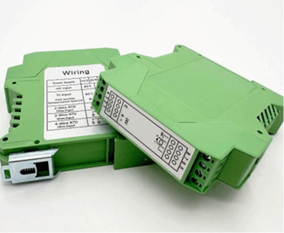
For instrument manufacturers, another crucial layer exists. This layer is the transmitter’s circuit board. The board takes the RTD signal. Next, it conditions and linearizes that signal. Then, it sends a temperature-proportional output directly to the control system. ICwalk provides this electronic core. We do not supply every complete field transmitter. Our H648WD temperature transmitter board is built for RTD and thermocouple inputs. It features an isolated 4-20mA output along with HART communication.

Start with the Calibration Goal
Before you gather your equipment, you must decide what needs verifying. A sensor-only check simply compares the RTD against a known temperature reference. Meanwhile, a transmitter calibration verifies something else. It checks if the board properly converts the sensor input into the right output. Finally, a loop check traces the signal. It follows this signal through the wiring and straight into the control system.
These various checks are closely related. However, they are never interchangeable. Sometimes, the temperature reading is incorrect. If you change transmitter settings before you check the sensor and wiring, you might hide the actual problem. You should always have a written procedure. This document must clearly state the sensor type, range, and test points. It should also list the expected output and note if any adjustments are allowed.
Tools Required for RTD HART Calibration
A good field kit brings together several items. It combines temperature simulation, electrical measurement, and communication tools. These instruments must have suitable ranges. They also need a current calibration status. You might work in hazardous locations. In these areas, your tools and work methods must strictly match the safety requirements of the site.
- RTD simulator or resistance decade source: This tool provides known resistance values. These values represent specific temperatures for your configured RTD type.
- Reference thermometer and temperature source: You will use a calibrated reference probe. You also need a dry block or a liquid bath. These are necessary when you check the actual sensor and its temperature response.
- Digital multimeter: This device measures loop current and supply voltage. It also checks continuity and resistance, provided the approved procedure allows it.
- HART-capable communicator: This tool reads device variables and configuration details. When supported, it gives you access to trim or calibration functions. You may use a Field Communicator 375. This is possible if it supports the specific HART revision and command set of the device.
- Loop power source or loop calibrator: This equipment supplies or measures the 4-20mA circuit. You use it primarily during bench testing.
- Wiring diagram and device configuration record: You must confirm terminal assignments and sensor wiring. You should also verify the range, damping, and output behavior before making any changes.
A smart field communicator never replaces a temperature reference or a multimeter. Instead, it communicates directly with the HART Protocol Module. Meanwhile, your other tools test the sensor input and the analog loop.
Check the Sensor and Wiring First
An RTD transmitter can sometimes report the wrong temperature. This happens even when its circuit module functions perfectly. Several factors can shift the reading. These include a damaged probe, a loose terminal, or an incorrect lead arrangement. A long cable with unwanted resistance can also cause issues. Therefore, you must start by confirming the sensor type. You should check the wiring against the actual instrument configuration.
The H648WD supports two-wire, three-wire, and four-wire RTD connections. It also works with multiple RTD and thermocouple types. Its product specifications list a DC10-32V supply. It features a 4-20mA output with HART communication and DC1000V isolation. The stated output accuracy is 0.1%. For thermocouple use, it features a cold-junction compensation error of 1°C. Keep in mind that these are strictly board specifications. The performance of a finished field transmitter relies on several other factors. These include its sensor, wiring, enclosure, installation, and the overall calibration process.
Calibration Steps for the Transmitter Board
Once you confirm the sensor and wiring, use the correct input source. This source must match the configured sensor type. Always follow the procedure from the instrument maker. You must also read the board documentation. Do not assume anything. Every HART transmitter does not use identical menus or trim commands.
- Record the existing sensor type. Also note the lower and upper range values, damping, and current output settings.
- Confirm the loop supply and wiring polarity. Ensure the load stays within the device limits.
- Connect an RTD simulator or a resistance source. Attach it to the correct input terminals.
- Apply at least three test values. These should include a lower-range, a middle-range, and an upper-range point.
- Compare the displayed or communicated temperature. Check it against the expected value at each distinct point.
- Measure the 4-20mA output carefully. Check that it accurately follows the configured range.
- Use the HART communicator to read the configuration and diagnostics. You should adjust settings only if the approved procedure requires it.
- Restore the normal sensor wiring. Next, verify the reading and record the final as-left values.
These steps help you distinguish a sensor-input error from an output-loop error. Sometimes, the HART reading is correct, but the measured current is wrong. In this case, you must investigate the output stage. Check the loop wiring, supply, and load. Do this before you change any sensor calibration.
Use HART for Configuration and Diagnostics
HART communication provides digital access over the standard analog loop. A field communicator can display the reported process temperature. It also shows sensor status, range settings, and useful diagnostic information. The exact options depend on the board and the final transmitter configuration. It may allow a technician to change range values. Alternatively, it might let them perform supported trims.
You might plan to use a Field Communicator 375 or another smart field communicator. Before doing so, confirm a few details. Ensure that the device description and command support of the communicator match the transmitter. Sometimes, the device is not recognized. If this happens, do not assume the board is faulty. Instead, check the HART wiring and loop resistance first. You should also verify the communicator support and overall configuration.
ICwalk’s H648WD is listed as an isolated temperature transmitter board. It features HART communication for junction-box installation. You might need other form factors. For those needs, the temperature transmitter board range also lists the H649WD. This model is for DIN-rail installation. Additionally, the H3051WD is available for a display housing.
Reduce Errors in the Cabinet and Field
Calibration results can easily change after installation. This occurs if the wiring environment differs from your test bench. You should keep low-level sensor wiring separate from power conductors whenever possible. Always use a suitable shielded cable. Furthermore, follow the system grounding plan. This practice helps reduce interference and lowers the risk of ground loops.
An isolated current transmitter can help separate parts of a process control board transmitter. However, isolation does not fix poor wiring or an unsuitable sensor. You might have a compact control cabinet. This cabinet might also contain a flow meter, pressure contact modules, drives, and relays. In such cases, check for noise and shared-ground effects. Perform these checks under normal operating conditions. You must test the complete loop using the final power supply and the actual control-system input.
ICwalk’s H648WD uses DC1000V isolation. It supports a wide range of RTD and thermocouple inputs. Its listed operating temperature ranges from -40°C to +85°C. These specifications provide very useful integration limits. However, they are not a blanket approval for every hazardous or corrosive service. You must evaluate the final instrument’s materials and enclosure. The installation and required certifications must also be reviewed for the actual site.
Why Instrument Manufacturers Choose ICwalk Boards
Why Instrument Manufacturers Choose ICwalk Boards: We solve the complex signal processing issues. We also handle the HART communication challenges. This support allows you to focus fully on mechanical design and process connections.
For an OEM, a temperature transmitter board acts as the measurement core. It sits inside a much larger product. The board handles sensor input and signal conditioning. It also manages linearization, isolation, and communication. The manufacturer remains completely responsible for other tasks. They must match the board with the probe, housing, and terminals. They also handle the process connection and any intended approvals.
dari ICwalk service team describes extensive support for multiple sensor inputs. They support HART and other communication options. They also offer customization and calibration software. ICwalk works as a Beijing-based business established in 2007. Today, the company serves customers in more than 50 countries.
Creating a high performance precision transmitter requires focus. This division of labor lets instrument makers concentrate their engineering time. They can focus on the sensor assembly and specific field requirements. Meanwhile, we address all the board-level electronics. Our process control board article discusses sensor matching and cable practices. It also covers important checks after integration.
Kesimpulan
Calibrating an RTD HART temperature transmitter requires specific items. You need a resistance or RTD simulator. You also need a suitable temperature reference when you check the actual probe. Furthermore, a multimeter or loop calibrator is essential, along with a compatible HART communicator. The correct steps always begin with the sensor type and wiring. After that, you check the configured range and the 4-20mA output. For instrument manufacturers, accuracy relies heavily on the transmitter board. It depends on the signal conditioning, isolation, and communication design. ICwalk’s H648WD is an isolated board component designed for OEM integration. It is not a complete field transmitter. We provide the robust circuit module and necessary HART functions. This allows manufacturers to build the sensor assembly and housing. They can then complete the process connection and the finished instrument for their own unique application.
FAQs
Pertanyaan: Can a HART communicator calibrate an RTD by itself?
A: No. It only communicates with the transmitter. You must use an RTD simulator or a reference source to test the input properly.
Pertanyaan: Does an RTD transmitter measure 5,000 L or 2,000 kg?
A: No. It only measures temperature. You need separate level, flow, or weighing instruments to measure volume or mass.
Pertanyaan: Can the Field Communicator 375 adjust every HART temperature board?
A: Not always. True compatibility depends on specific device support. It also relies on the HART revision and the available commands.


