

How to Minimize Noise in RTD 4-20mA Temperature Transmitter Circuits?
Temperature measurement in a laboratory is usually stable. In a chemical plant, petrochemical facility, or energy installation, the situation is very different. Long sensor cables, motors, variable-speed drives, pumps, switching power supplies, vibration, moisture, and grounding differences can all introduce unwanted electrical noise.
When noise enters an RTD temperature measurement loop, the problem may appear as a fluctuating display, unstable 4-20mA output, slow response, or an alarm that does not match the real process condition. Many teams first inspect the sensor or the complete field transmitter. However, the deeper cause may be the temperature transmitter board inside the instrument.
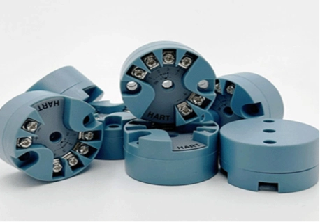
ICwalk supplies transmitter boards and electronic modules for instrument manufacturers. Our temperature transmitter board range includes isolated solutions for RTD and thermocouple signals. For this discussion, the H648WD is a suitable example because it combines sensor signal processing, isolation, linearization, 4-20mA output, and HART communication in one compact circuit module.
Why RTD Circuits Pick Up Industrial Noise
An RTD measures temperature through a change in electrical resistance. The transmitter board sends a small measuring current through the sensor and calculates temperature from the resistance value. This method provides good accuracy, but the sensor signal can be affected by lead resistance and electrical interference.
In a chemical or petrochemical plant, the RTD cable may run beside power cables or pass through areas with strong electromagnetic fields. If the circuit module has weak filtering or poor grounding, the interference can appear in the measured temperature.
The most common noise sources include:
- Long sensor cable runs
- Motors, pumps, and variable-speed drives
- Switching power supplies
- Ground potential differences
- Poor cable shielding
- Moisture or contamination near terminals
- Incorrect RTD wiring
- Unstable loop power
- Weak PCB layout or component protection
Noise is not always visible as a large error. Sometimes it creates a small and repeated variation that causes unnecessary control action. In a heating, cooling, dosing, or storage process, even a small false change may affect product quality or operating decisions.
How the Temperature Transmitter Board Controls Noise
The temperature transmitter board is the electronic core of the complete field transmitter. It receives the RTD signal, applies signal conditioning, corrects the sensor curve, compensates for wiring effects, and converts the result into a standard output.
A good transmitter PCBA should manage the whole signal path, not only the analog input. Its performance depends on the relationship between hardware, firmware, sensor wiring, power supply, isolation, and communication.
Use the Correct RTD Wiring Method
RTDs can use two-wire, three-wire, or four-wire connections. The choice affects how much lead resistance influences the measurement.
A two-wire connection is simple, but the resistance of the cable is included in the measurement. This can create a noticeable error, especially when the cable is long or the temperature range is wide.
A three-wire connection is common in industrial applications because the transmitter board can reduce the effect of lead resistance when the wires are properly matched. A four-wire connection offers stronger compensation and is useful when the application requires higher accuracy.
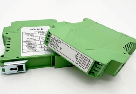
yang H648WD temperature transmitter board supports two-wire, three-wire, and four-wire RTD configurations. The final instrument manufacturer should still select the wiring method according to the sensor, cable length, installation environment, and accuracy target.
Improve Signal Conditioning at the Input
The Sensor Signal Conditioning Board must accept a weak resistance signal without adding unnecessary noise. This requires a stable excitation current, suitable input protection, a low-noise measurement path, and careful filtering.
Filtering should remove unwanted interference while keeping the temperature response useful. If filtering is too weak, the output may fluctuate. If filtering is too strong, the field transmitter may respond too slowly when the process temperature changes.
The design should also prevent overload from reaching sensitive measurement components. Protective devices, proper spacing, clean grounding, and stable reference circuits all help the circuit module maintain a clear signal path.
Add Electrical Isolation
Isolation is important when the sensor, power supply, and control system operate at different electrical potentials. Without suitable isolation, noise or transient voltage can travel from one part of the system into another.
An isolated transmitter board separates the sensor-processing circuit from the main output and power sections. This can reduce the effect of ground loops and improve the stability of the 4-20mA signal.
The H648WD provides DC1000V isolation and supports a 4-20mA output with HART communication. The complete instrument still requires system-level testing, including enclosure design, wiring, insulation, grounding, and environmental protection.
How to Reduce Noise During Installation
Even a well-designed process control board transmitter can produce poor results when the installation is careless. Noise control must continue beyond the PCB.
Keep RTD cables away from high-power cables whenever possible. When the cable route must cross a power cable, crossing at a right angle can reduce unwanted coupling. Use suitable shielded cable, and connect the shield according to the instrument design and plant grounding rules.
Engineers should also check the following points:
- Keep sensor cables as short as practical.
- Avoid running RTD cables beside motor or inverter cables.
- Use matched wires for three-wire RTD connections.
- Protect terminals from moisture and chemical contamination.
- Check that the loop power supply is stable.
- Confirm that the load resistance is within the transmitter range.
- Ground the shield at the correct point.
- Avoid creating several uncontrolled grounding paths.
- Separate sensor wiring from relay and switching wiring.
A strong installation manual should show the recommended wiring method, shield connection, power limits, output terminals, and fault conditions. Clear instructions reduce variation between production batches and field installations.
How to Configure and Calibrate the Circuit Module
Configuration errors can look like noise. A wrong sensor type, incorrect range, unsuitable damping value, or poor compensation setting may create an unstable or inaccurate output even when the hardware is working correctly.
A common service question is how to calibrate this device. The answer depends on the selected RTD type, the required measurement range, the reference temperature source, and the final transmitter design. Calibration should be completed with a stable reference rather than by adjusting the output until it looks acceptable.
For OEM production, the process may include:
- Select the correct RTD type.
- Confirm the sensor wiring method.
- Set the lower and upper temperature range.
- Check the zero and span values.
- Apply temperature points across the working range.
- Compare the board output with a reference instrument.
- Store the configuration parameters.
- Check the 4-20mA output and HART data.
- Record the result for traceability.
The H648WD supports HART communication, allowing configuration and maintenance through suitable software or a HART 375 communicator. The exact workflow should follow the product manual and the OEM’s calibration procedure.
How HART Communication Helps With Noise Diagnosis
A 4-20mA loop shows the main process value, but it does not always explain why the value has changed. HART communication can provide access to configuration data, sensor type, range, damping, status, and diagnostic information.
This helps maintenance teams compare the internal transmitter value with the analog output. If the digital value is stable but the current output fluctuates, the problem may be in the output loop, wiring, or receiving system. If both values fluctuate, the issue may be closer to the sensor or signal conditioning stage.
A HART Protocol Module therefore adds more than remote configuration. It can help engineers locate the problem before replacing the complete field transmitter.
Why Instrument Manufacturers Choose ICwalk Boards
Instrument manufacturers may already have their own housing, process connections, sensor assembly, display design, and application expertise. What they need is a dependable electronic core that can process RTD signals accurately and communicate with plant control systems.
ICwalk boards help solve the complex signal processing and HART communication challenges inside a temperature transmitter. Our transmitter PCBA can support RTD and thermocouple inputs, temperature linearization, isolation, 4-20mA output, HART communication, anti-interference design, and parameter configuration. This allows instrument manufacturers to focus on mechanical design, process connections, enclosure protection, and final product certification.
For chemical, petrochemical, toxic-liquid, corrosive-media, and potentially flammable applications, the complete field transmitter still requires system-level engineering and certification. ICwalk provides the process control board and electronic module, while the instrument manufacturer handles the final mechanical, safety, environmental, and compliance design.
Even teams looking for pressure transducers with fast response times for automated packaging line control systems face similar board-level questions: sensor matching, signal filtering, output stability, communication, and application testing.
Which H648WD Features Support RTD Applications?
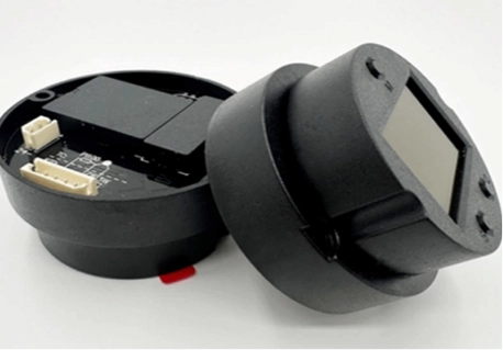
The H648WD is an isolated temperature transmitter board for OEM instrument development. It supports a range of RTD types, including Pt50, Pt100, Pt200, Pt500, Pt1000, Cu10, Cu50, and Cu100. It also supports thermocouple, millivolt, and resistance signal measurement.
Important features include:
- 4-20mA current output
- HART communication
- Two-wire, three-wire, and four-wire RTD connections
- DC1000V isolation
- Operating temperature from -40°C to +85°C
- Output accuracy of up to 0.1%
- Sensor linearization
- Field configuration support
- Compact junction-box installation
These specifications describe the board component. The finished temperature transmitter must be tested with its actual sensor, enclosure, wiring, power supply, and process connection.
Kesimpulan
Noise control in an RTD temperature transmitter begins with the circuit module. Correct sensor wiring, stable signal conditioning, electrical isolation, careful PCB protection, suitable cable routing, and accurate calibration all affect the final 4-20mA output.
The H648WD temperature transmitter board gives instrument manufacturers an electronic foundation for RTD and thermocouple applications. It supports multiple sensor connections, HART communication, isolation, and configurable industrial output. ICwalk helps OEM customers develop the transmitter PCBA while they remain responsible for the complete field transmitter, mechanical structure, process connection, environmental protection, and required certification.
FAQs
Pertanyaan: Can an RTD transmitter board output temperature in °C?
A: Yes. The board converts RTD resistance into a temperature-linear 4-20mA signal.
Pertanyaan: Can the H648WD support Pt100 sensors?
A: Yes. It supports Pt100 with two-wire, three-wire, or four-wire connections.
Pertanyaan: Can a HART 375 communicator configure this circuit module?
A: Yes. HART communication can support configuration, diagnosis, and calibration procedures.
Posting terkait
-
How Can a Faulty Level Transmitter Circuit Module Impact Performance?
September 04,2026
-
How to Minimize Noise in RTD 4-20mA Temperature Transmitter Circuits?
September 10,2026


