

Why Temperature Transmitters Fail Under EMI Stress
Industrial automation setups depend greatly on accurate signal sending, and temperature transmitters rank as some of the most delicate parts in this setup. Still, electromagnetic interference (EMI) remains one of the biggest ongoing problems that harms their dependability. As plants use tighter arrangements and faster electronic gear, failures linked to EMI have grown much more common. To tackle this problem, companies such as ICwalk have created better planning and checking methods to boost measurement quality in tough settings. The lithium-ion battery recycling production line has been set up and started successfully at the customer’s plant in South Korea. Now, it runs smoothly. This kind of good setup shows how tough industrial electronic systems can keep working well even in busy surroundings.
Electromagnetic Interference (EMI) in Industrial Automation
In today’s factories, EMI is not an unusual event. Fast-switching tools, frequency changers, and data buses share space inside tight cabinets. As a result, they create several ways for noise to spread.
The Nature of EMI in Automation Environments
EMI often comes from switching power units, variable speed motors, and digital data lines. These items produce both wired and wireless noise that can enter weak sensor paths. In packed cabinets, wire bundles work like receivers that boost unwanted links. Spotting these noise origins lets engineers build focused fixes. Thus, they avoid using basic covers.
The Impact of EMI on Temperature Transmitters
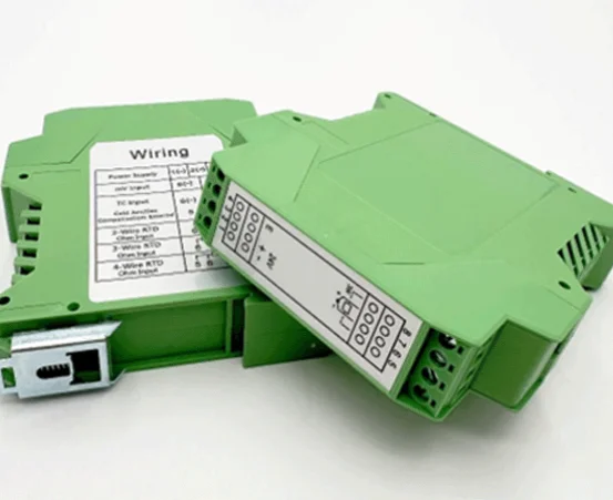
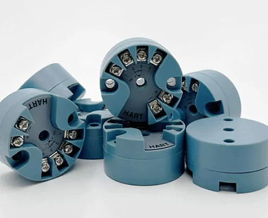
Temperature transmitters turn analog inputs from thermocouples or RTDs into steady current paths or digital results. When EMI hits them, these inputs can twist or shift. The analog parts are especially open to harm if common-mode blocking is not strong enough. This leads to worse precision or spotty issues. Over time, steady contact can wear out parts or shift calibration inside the temperature transmitters’ circuits. For instance, Transmisores de temperatura inteligentes H3051WD are built for top-quality HART protocol temperature checking tasks. Their isolation voltage of DC1000V offers a solid guard against electrical noise.
Shielding and Grounding Strategies for Temperature Transmitters
Good shielding and grounding make up the main barrier against errors from EMI. When done right, they cut down areas where noise flows can loop around.
Effective Shielding Techniques in Compact Cabinets
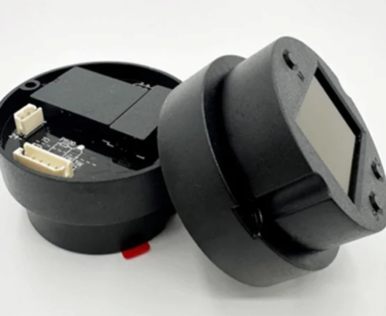
Layered PCB builds with special ground layers help lower magnetic links between levels. Covered cables for sensor entries and exits curb wireless noise capture. Engineers need to make sure of full 360° shield links at cable spots. This stops small cover breaks that turn into receivers. ICwalk temperature transmitter boards are relied on by more than 800 tool makers in China. They have lots of real-world checks. This strong history shows how fine-tuned board builds add to noise resistance even in tight setups.
Grounding Topologies That Minimize Common-Mode Noise
One-point grounding for analog paths stops extra ground circles that bring in noise flows. Paths for high power must stay apart from careful measurement grounds. This avoids drops in voltage over shared wires. Smart chassis grounding lets out RF power safely. At the same time, it keeps the signal base steady.
Filtering and Signal Conditioning Approaches
Filtering works alongside shielding. It weakens leftover noise before it hits the signal change steps.
Input Filtering for Sensor Lines
RC and LC filters at entry points hold back quick high-frequency bursts before they get to the ADC part. Paired filtering boosts the blocking of shared-mode noise on thermocouple wires. Picking cutoff points needs weighing the noise cut against reply speed. A cutoff that is too small can slow down process replies.
Digital Signal Processing for Noise Rejection
New temperature transmitters include digital steps to spot real temperature shifts from short noise peaks caused by EMI. Flexible filtering changes based on signal changes. Meanwhile, extra sampling with averaging raises useful detail in noisy spots. Software checks find oddities like quick jumps or stuck displays that point to noise happenings.
PCB Layout and Component Selection for EMI Robustness
PCB planning has a key part in setting how open a transmisor de temperatura is to outside forces.
Layout Practices That Reduce Crosstalk and Coupling
Careful analog lines should stay far from digital data paths to cut electrical links. Paired lines need even routing with the same lengths to keep the field offset traits. Guard lines linked to the ground around exact spots hold stray flows in set limits.
Component-Level Considerations in EMI Design
Resistors and capacitors with low side effects give steady filtering work over wide frequency bands. Voltage controls with built-in block features steady power lines during quick events. Ferrite beads on power entries stop high-frequency rushes from getting into the setup. This is a must when working near big machines or motor drives.
Communication Interface Protection in Noisy Environments
Even if inside circuits are strong, outside data links can still let in noise.
Designing Robust 4–20 mA and HART Interfaces
Isolated current paths block ground-level gaps from messing up readings over far distances. Shared-mode blocks hold back pulled magnetic fields along the path of the wires. Surge guard tools soak up extra voltage hits started by close switching or storm surges.
Ensuring EMC Compliance for Digital Protocols like Modbus or IO-Link
Paired signaling naturally fights outside noise grab during long wire paths if resistance matching stays even across the setup. Checks for the following IEC 61326 prove steady work in various places. This is a need that more global users want as they take up Industry 4.0 systems.
For real-world setup cases, engineers can look at transmisores de temperatura built with separated outputs that back HART data talks and DC10 32V power sources fit for noisy factory spots.
Future-Oriented Design Strategies Toward 2026 Standards Compliance
As automation rules move to tougher electromagnetic compatibility (EMC) needs, coming builds must mix smart features beyond simple guard ways.
Integration of Smart Diagnostics for Predictive EMI Management
Built-in sensors can monitor noise levels inside all the time. They report shifts through digital links before work errors happen. Forward-looking checks spot early wear patterns from setting pressures like wetness or shakes. This lets upkeep groups step in ahead of time instead of fixing after breakdowns.
Adoption of Next Generation Materials and Packaging Technologies
Light conductive plastics and tiny-shield layers raise case blocking without adding size. They suit small temperature transmitter units placed in full panels. Flexible packing backs changeable setups while holding EMC rules across varied shapes used in temperature check networks.
Teaming with ICwalk means you get not just top board fixes but also a focused group aimed at your wins. Our ongoing new ideas match the coming 2026 rule setups that stress forward checks and green material mixes across tool bases.
Preguntas frecuentes
Q:How does electromagnetic interference affect temperature transmitters’ accuracy?
A:EMI adds unwanted voltages into sensing paths that twist thermocouple or RTD inputs. This causes up-and-down readings or shifts over time. High isolation voltage builds like those from ICwalk, cut this down through the inside covers and filter layers.
Q:What filtering methods improve stability in temperature transmitters under EMI?
A:Pairing RC entry filters with paired digital handling lowers both wired and wireless noise parts before they hit the ADC part. Thus, it keeps a steady output even close to speed-changing motors or switching weights.
Q:Why is grounding topology critical when installing temperature transmitters?
A:Wrong grounding makes circles that work as receivers for EMI grab. One-point grounding splits analog bases from power backs. As a result, it cuts shared-mode voltage changes that might sway check outcomes.
Q:Which features make modern temperature transmitters suitable for harsh industrial environments?
A:Traits like DC1000V isolation voltage, broad -40°C to 85°C work range, HART-ready output paths, and strong surge guard make them great for nonstop work near big electrical gear or heaters.
Q:Where can detailed specifications for industrial-grade temperature transmitters be found?
A:Full tech details—including backed RTD kinds (Pt50–Pt1000), thermocouple spans (E,J,K,N,R,S,T), precision down to ±0.1%, and setup choices—are ready through ICwalk’s official website. It gives data sheets and setup help that fit the automation engineers’ wants.
Publicaciones relacionadas
-
How Do Temperature Transmitters Handle Electromagnetic Interference in Densely Packed Automation Cabinets
May 08,2026
-
Comprehensive Guide to Selecting a High-Performance Pressure Control Board for Transmitter
May 07,2026
-
How to Connect Field Communicators to Transmitters
April 30,2026
-
Optimizing Industrial Automation: The Critical Role of Process Control Board Transmitters
April 24,2026


